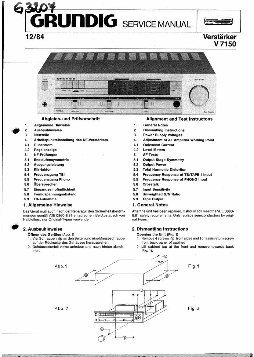
Grundig V 7150 Service Manual

This is the 6 pages manual for Grundig V 7150 Service Manual.
Read or download the pdf for free. If you want to contribute, please mail your pdfs to info@audioservicemanuals.com.

Page: 1 / 6
left right
Grundig V 7150 Service Manual

Extracted text from Grundig V 7150 Service Manual (Ocr-read)


Page 1

6 .
fiunDIG SERVICE MANUAL

12/84

Verstéirker
V 7150

Abgleich- und Priifvorschrift

Allgemeine Hinweise

Ausbauhinweise

Netzteile

. Arbeitspunkteinstellung des NF-Verstérkers
4. Ruhestrom

4.2 Pegelanzeige

5. NF-Prtlfungen /
5.1 Endstufensymmetrie

5.2 Ausgangsleistung

5.3 Klirrfaktor

5.4 Frequenzgang TBI

5.5 Frequenzgang Phono

5.6 fibersprechen

5.7 Eingangsempfindlichkeit

5.8 Fremdspannungsabstand

5.9 TB~Autnahme

1. Allgemeine Hinweise

Das Gerat mul3 auch nach der Reparatur den Sicherheitsbestim-
mungen geméB VDE 086043.81 entsprechen. Bei Austausch von
Halbleitern. nur Original-Typen venNenden.

WP?

O 2. Ausbauhinweise

bffnen des Gerates (Abb. 1)

1, VierSchrauben @ an den Seiten und eine Masseschraube
auf der Ruckseite des Gehauses herausdrehen.

2. Gehauseoberteil vorne anheben und nach hinten abneh-
men.

Abb.1

Abb. 2

Al gnment and Test lnstructons

1 General Notes

2. Dismantling Instructions

3. Power Supply Voltages

4. Adjustment of AF Amplifier Working Point
4.1 Quiescent Current

4.2 Level Meters

5. AF Tests

5.1 Output Stage Symmetry

5.2 Output Power

5.3 Total Harmonic Distortion

5.4 Frequency Response of TBIT APE 1 Input
5.5 Frequency Response of PHONO Input

5.6 Crosstalk

5.7 Input Sensitivity

5.8 Unweighted SIN Ratio

5.9 Tape Output

1. General Notes

Atterthe unit has been repaired, it should still meet the VDE 0860-

8.81 safety requirements. Only replace semiconductors by origi-
nal types.

2. Dismantling Instructions
Opening the Unit (Fig. 1)
1. Remove 4 screws @ from sides and 1 chassis return screw
from back panel of cabinet.
2. Lift cabinet top at the front and remove towards back
(Fig. 1).

Fig.2