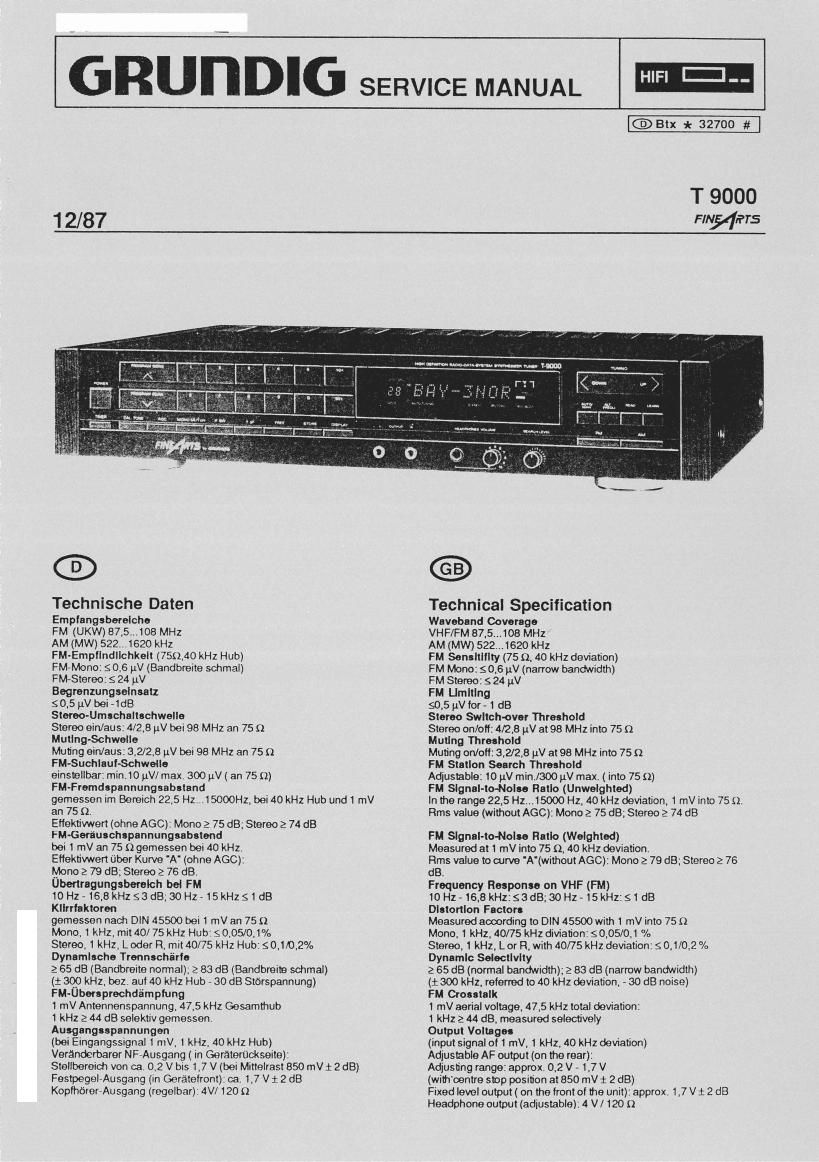
Grundig T 9000 Service Manual

This is the 38 pages manual for Grundig T 9000 Service Manual.
Read or download the pdf for free. If you want to contribute, please mail your pdfs to info@audioservicemanuals.com.

Page: 1 / 38
left right
Grundig T 9000 Service Manual

Extracted text from Grundig T 9000 Service Manual (Ocr-read)


Page 2

lnhaltsverzelchnls Seite
Tectmieche Dalen 1
Allgemeine Hinweise 2
Auebauhlnweile 3-4
Ersatzteilliste 58
Bedenungshinweise 9
Sdialmngsbesdveibung:

- RDS - Daren 10-11
- New 1 1

- i» 15 V NW 1 1-12
- Die negativen Spammgen 12

- Heizung for Anzeige 12

- Ausscheltllackemnmodmng 12

- 31 V Netzteil 13

- Die Synthesizer 13.15
- Abglolch der Reterenzdose 14

- Service (Testmode) 14

. Signalweg 16

. Mischteil 16

- ZF - Verstfirker , 16.18
- AGG (Automatic gain control) 16.17
~ Bancbteitenumochaltung 18
- PLL - Demoduhhr 19

- Suchiautnuswertmg und Feidstanteanaeige 19

- FM . Abgleioh ' 19.20
- Aec - Abgldch a0

- AM - Abgtolch 20

- Ahgleleh Feldstfirltoenzeige AM 20
- HOS - Demoduiatorund Abglolch 21

- PLL-Stereo-Decoderundnbglolch 22
- Kalibrlemngenerlbr und Abglololl 22

- Computerpiatte 22.23
- Display 23,24
- Abglolch FM - Feldstarlcaanzeige 24
Abgteichlageplan 25
AuschluBrabelle des Displays 26
Symbolerklérungen 27,25
Druckplalten 29-32
Schaltbild 33-44

Allgemelne Hlnwelse

Contents Page
Technical Specification 1 ,

General Notes 2

Disusembty instructions 34

Spare Parts List 5-6

Instruction notes 9

Circtrit Disctiption:

- RDS Data 10-1 1

- Maim part 11

- +15V|IdinsPart 11-12

- The negau've Voltages 12

- Heating tor the Display 12

~ Suppression ol the flashing during the 12
switching - oft

~ 31 V Mains part 13

- Synthesizer 13,15

~ Allgnment of the reference box 14

- Service (T estrnode) 14

- Signal path 16

- Mixer ts

- lFemplifier 18,12

- AGO (Automatic gain control) 18.17

- Bandwidth switching 18

- PLL Derricduleter 19

~ Snltseok evaluation and field strength 19 1,:
Mcation ,

- FM Alignment 19.

- AGO Alignment 20

- AMAllgrmrt 20

- Adustmentof the field strength indication 20

- ROS demomw and alignment 21 _

- PLLStereodecoderandaligmnent 22 °

- Calibrating tone generator and alignment 22

- Computer panel 22.23

- Display 23.24

- Alignment ol the FM lieldstrength indication 24

Alignment layout 25

Comectirig diagram of the display 26

Discription at symbols 27.28

Printed circuit boards 2932 v

Connecting diagram 3344

General Notes

Bel Elngrltlon Scttutnnennahmon tilt MOS-Bundle
bucht-nl '

N.B. When carrying out repairs, observe M03
precautions l

Das Gerat mull auch nach def Reparatur den Sicherheits-
bestimmungen nech DIN I IEO 65 VDE 0660mtsprechen.

Masseverbindungen zum Chassis Wen nid'it verandert warden.
damit das Gert-1t den Postvorschritten entspricht

Der Abgleich der einzetnen Baugruppen ist in der lewelligon
Sahaltungsbeschreibung enthalten.

After the unit has been eraired, it should still meet the DIN/lEO 65
VDE 0860 salety requirements

The ground connections to chassis must not be changed as
otherwise, the model is no longer in compliance with the postal
specifications at the respective country.

The alignment at the individual modules forms pm of the mpedvo
circuit description.