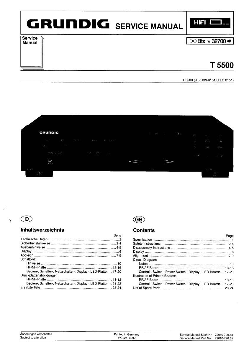
Grundig T 5500 Service Manual

This is the 24 pages manual for Grundig T 5500 Service Manual.
Read or download the pdf for free. If you want to contribute, please mail your pdfs to info@audioservicemanuals.com.

Page: 1 / 24
left right
Grundig T 5500 Service Manual

Extracted text from Grundig T 5500 Service Manual (Ocr-read)


Page 1

.J

G RU n DIG SERVICE MANUAL

Service
Manual

T 5500

T 5500 (9.5513948151/GLC 0151)

GRUIIDIG

GD)

lnhaltsverzeichnis

Technische DaIen r
SIcherheilshinweise
Ausbauhinweise,
Display
Abgleic
Schallbild:
Hinweise
HF/NF Bedien-, Schalter-, Netzschalter-, DIsplay-, LED-Planen 1 7-20
Druckplanenabbildungen:
HF/NF Plane
Bedien Schaller-n Nelzschalten Display LED Flatten .
Ersatzteilliste

Contents

Specification
Safety Instructions
Disassembly Instructions
Display
Alignment
Circuit Diagram
Notes
RF/AF Board
ControI-, Switch, Power Switch Displa
Illustration of Primed Boards:
RF/AF Board
Control, Switc Power Swnch Disola LED Boards
Listof Spare Pans. .


LED Boards

Anderungen vnrbahallen
Subjaci to alteralion

Printed in Germany
VK 225 0292

Service Manual Sach-Nr 72010-720155
Servroe Manual Pan No. 72010-72065

Page 2

r r'r'nnm'ne uaren. orr'mrnuismruVin/rm / open/u urirm, oujery Requirement;

Technische Daten

Emptangsbereiche:
FM ..................
MW (manual tuning)

MW (automatic tuning)
MW (USA»Version) ......

...87,5...108 MHZ
525...1805 kHz
31...1602 kHz
.520...1620 kHz


FM-Abstimmraster: ...... Suchlauf 50 kHz/Handabstimmung 25 kHz

FM-Empfindlichkeit (75D, 40 kHz Hub)
UKW-Mono: ..1 pV fur 26 dB Signal/Rausch-Abstand
UKW-Stereo ( 5 uV For 46 dB Signal/RauschsAbstand


Muting-Schwelle: .................................................................... 15 pV

FM-Fremdspannungsabstandz

gemessen im Bereich 31,5 Hz...15000 Hz, bei 40 kHz Hub und1 mV
an 75 £2. Spitzenwert nach DIN 45405/Effektivwert

Mono ............................................................................ 267/71 dB
264/68 dB

Stereo

FM-Geréuschspannungsabstand:

Bei 1 mV an 75 Q gemessen be! 40 kHz.
Spitzenwert nach DIN/Effektivwert fiber Kurve »A«
Mono
Stereo ,.

Ktirrfaktor

gemessen nach DIN 45500 bet 1 mV an 75 a

Mono 30.2% bei 1 kHz und 40 kHz Hub
Stereo . .SO,4% Del 1 kHz und 40 kHz Hub


Dynamische Trennschérte
:v 300 kHz. bez. aut 40 kHz Hub. -30 dB Stdrspannung

Mono ....................................................................................... 280 dB
Stereo ..................................................................................... 270 dB
Ausgangsspannung: ...................... 650 mV (+15 -20 %) an 1,7 kn

Specification

Waveband Coverag
FM

MW (manua unlng) ...1605 kHz
MW (automatic tuning) ,..1602 kHz
MW (US version) ........ ...1620 kHz

FM Tuning steps: tttttt Station search 50 kHz/Manual tuning 25 kHz

FM Sensitivity (75S). 40 kHz deviation)
UKW-Mon '.1 uV at 26 dB signal/noise ratio
UKWrStereo ( Is a ). 35 W at 46 dB signal/noise ratio


IF Suppression:
UKW
MW:

>120 dB
...t47 dB

Muting Threshold: .................................................................. 15 uV

FM-Signal-to-Noise Ratio (Unweighted):

In the range 31.5 Hz... 15000 Hz, 40 kHz deviation and 1 mV into 75 Q.
Peak value according to DIN 45405/rms value

Mono .................................................................................. 267/71 dB
Stereo ................................................................................ 264/68 dB

FM-Signal-to-Noise Ratio (Weighted):

Measured at 1 mV into 75 n, 40 kHz deviation.

Peak value according to DIN/rms value to curve »A«'
Mono
Stereo .

Distortion Factor
Measured according to DIN 45500 at 1 mV into 75 Q

Mono .. 502% at 1 kHz and 40 kHz deviation
Stereo 50.4% at 1 kHz and 40 kHz deviation
Dynamic Selectivity

: 300 kHz, referred to 40 kHz deviation, 730 dB noise

Mono ....................................................................................... 280 dB
Stereo ..................................................................................... 270 dB
Output Power: ................................ 650 mV (+15 20 °/o) into 1,7 kn

Sicherheitsvorschriften / Safety requirements / Prescrizioni de sicurezza/
Prescriptions de sécurité/ Prescripciones de seguridad

Achtung: Bel Eingriffen ins Gerat sind die Sicherheitsvor~
schriften nach VDE 701 (reparaturbezogen) bzw. VDE 0860
/ IEC 65 (geratebezogen) zu beachten!

Bauteile nach lEC- bzw. VDE-Richtlinien ! lm Ersatztall nur
AA Teile mit gleicher Spezifikation verwenden!

MOS - Vorschritten beim Umgang mit MOS - Bauteilen
beachten!

Attention: Please observe the applicable safety require-
ments according to VDE 701 (concerning repairs) and VDE
0860/ IEC 65 (concerning type of product)!

&A Components to IE0 or VDE guidelines! Only use compo-
nents with the same specifications for replacement!

Observe MOS components handling instructions when ser-
vicing!

® Attenzione: Osservarne le oorrispondenti prescriztoni di
sicurezza VDE 701 (concernente servizio) e VDE 0860/ IEC
65 (concernente il tipo di prodotto)!

AA Componenti secondo le norme VDE risp. to IE6! In case di
sostituzione impiegare solo ccmponenti con le stesse carat-
teristiche.

Osservare Ie relative prescrizioni durante, Iavon con compo-
nenti MOS!

® Attention: Priere dobserver les prescriptions de securite
VDE 701 (concernant les reparations) et VDE OSGO/lEC 65
(concernant le type de produit)!

Composants répondant aux normes VDE ou IEC. Les rem-
placer uniquement par des composants ayant les memes

spécilications.

Lors de la manipulation des circuits MOS. respecter les
pescriptions MOS!

® Atencion: Recomendamos las normas de seguridad VDE u
otras normas equivalentes, por ejemplo: VDE 701 para
reparacnones. VDE 0860 / IE: 65 para aparatos!

Componentes que cumplen Ias normas VDE/lEC. En caso
de sustitucion, emplear componentes con idénticas especi<
ficaciones!

Durante la reparacion observar Ias normas sabre com-
ponentes M03!

120 V/SO Hz. Also observe the information given on the rear
01 the set.

CAUTION-for continued protection against risk of fire res
place only with same type fuses!

CAUTION: to reduce the risk at electric shock, do not remove
cover (or back). no user-serviceable parts inside, refer
servicing to qualified service personnel. Observe MOS
components handling instructions when servicing!

® Attention: This set can only be operated from AC mains of
U.S.&
Canada

GRUNDIG Service»Technik