Grundig Sonoclock 350 Service Manual

This is the 25 pages manual for Grundig Sonoclock 350 Service Manual.
Read or download the pdf for free. If you want to contribute, please mail your pdfs to info@audioservicemanuals.com.

Page: 1 / 25
left right
Grundig Sonoclock 350 Service Manual

Extracted text from Grundig Sonoclock 350 Service Manual (Ocr-read)


Page 2

Abgleich- und Prijfvorschrift fiir Elektronikuhr-
Einbaumodul

Allgemeines:

Zur Betriebsspannungsversorgung und zur Uberpriifung der ain-
zelnen Schaltfunktionen muli die Uhr an ein entsprechendes
sono~clcck~Gerat oder an eine spezielle Prufvorrichtung ange-
schlossen werden. An der Riickseite der Uhr sind hierfur zwei
Steckverbindungen (Batterie und GerateanschiuB) angebracht.
Die genaue Kontaktbelegung kanndem Schaltbild entnommen
warden.

1. Netzbetrieb:

Betriebsartenwahl :

Betriebsartenschalter der Uhr in Stellung y,AUS" bringen und
Gerat an 220V Netzspannung anschlieBen Dabei darf sich der
Empfanger nicht selbsttatig einschaltenI Zur Aktivierung aller
Uhrenfunktionen muB zunachst die Taste ,,rnin/MON" gedriickt
werden. Eventuell vorhandene Striche im Display warden

und I,h/Tag" eine Uhrzeit von 2359 Uhr einstellen. wahrend des
gesamten Einstellvorgangs Anzeige beobachten und Aufleuch-
ten other 7 Segmente je Ziffer kontrollieren. Bel der Zehnerstelle
der Stundenanzeige ist das Segment F1 nicht angeschlossen,
Setzhebel in Stellung wDA bringen und festhalten. Gleichzeitig
Taste ,,minlMON" und anschlieliend Taste ,,h/TAG" betatigen bis
Datum 28.2. erecheint.

Nach Ablauf einer Minute miissen folgende Anzeigen aufleuch-
ten:

Uhrzeit 0. 00

Datum; ' 1 3

Betriebsartenschalter in Stellung ,,AUS" bringen und Taste
,,Schlummer" betatigen, Empféinger schaltet sich sofort ein
wahrend des Setzvorgangs Wird an Stelle der Uhrzeit die einge~
tastete Einschaltdauer angezeigtI Taste ,,ResetlAIarm- Pause."
driicken, Empfanger schaltet sich aus. _

9 natteltiebetrieb

dadurch Qeloscht.
Schalter In Stellung ,,EIN": ,
Sci-latter in Stellung .,AUT"

Empfa'ngar' In Betrieb. 'xk
Empfanger spatestensnach'
_ einer Sekunde In etri _
Bleibt das Gerat trotzdem ausgeschaltet, ist le angezeigte Uhr-
zeit mit der Weckzeit die In Stellung ,,WECK" des Setzschalters
erscheint, auf Ubereinstimmung zu iiberpriifen und notfalls ent-
sprechend zu korrigieren.

Automatlsche Netz-Batterle-Umschaltung:
In die Zuleitung zur Batterie (ersetzt-durch Netzteil, U3 = 7,5 V)
ist ein Amperemeter zu schalten und der in die Batterie hinein-
flieBende Strom bei Netzbetrieb zu messen: ,

I= < 10 IA
7- -Segment-Anzeige und Setzfunktionen:
Nacl'l AnschluB an die Netzspannung leuchten auf der LED- An~
zeige in der Regel drei waagrechte Striche vereinzelt auch Zah-
Ien (LB. Null) auf. Der Punkt zwischen StundenA und Minutenan-
zeige blinkt imSekundenrhythmus.Taste "Uhrzeit"drucken,fes'tv
halten ~Sekundenpunkt erlischt - und mit den Tasten,,min/MON"

Oszillatorabgleich

~ Gerat vom Netz trennen Anzeige erlischt nach kurzer Zeit, nur
Sekundenpunkt .in kt' lm Sekundenrhythmus weiter.


Nacn Weohseln es muii der Oszillator neu abgeglichen
werden. Eine Batteriespannung von 8 3V einstellen und Gerat

- vom Netz trennen. KurzzeitmeBgerat (z. B GRUNDIG Universal-

zahler UZ 56 S) an Punkt 36 des lCs anschlieBen und die Zeit
zwischen zwei ansteigenden Flanken dos IHz-Rechtecksignals
messen. Der Oszillator (f- = 100kHz) ist nun mit Hilfe des Reglers
R201 so einzusteller'l, daB sich am MeBpunkt eine Periodendauer
von 1000 i 10ms ergibt.

Automatische Netz-Batterie-Umschaltung:
Mit Amperemeter in die Uhr hineinflieBenden mittleren Strom bet
voll aufgedrehter Helligkeit der Anzeige messen:

I ~ 10 18 mA

AnschlieBend die Alarm lBatterie Abschalttaste so lange dril'k-
ken. bis Sekundenpunkt erlischt Der Punkt darf beim Loslassen
der Taste nicht wieder aufleuchten.

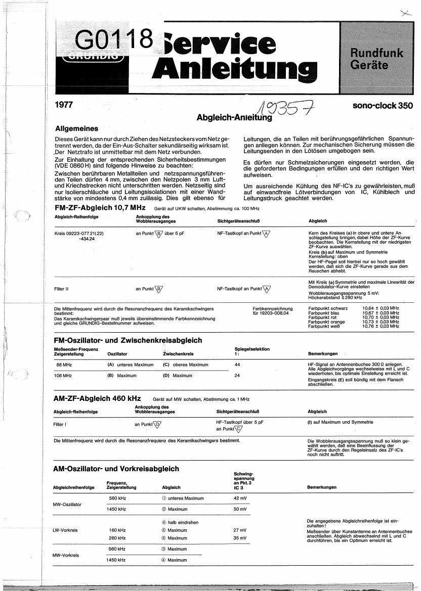
Alignment Instruction

General

To disconnect from mains supply remove mains plug, as the
on/otf switch is in the secondary and the transformer is con-
nected directly to the mains supply. To comply with the
required safety regulations (VDE 0860 H) observe the following:
Between the bare- metal parts and the mains-conducting
parts the minimum air- and creepage distance is 4 mm, between
the mains poles 3mm. Isolating sleeves and circuit insulations
must have a thickness of at least 0,4 mm. This is also applicable
for tleads which could come in contact with voltage carrying
par 3.

FM-lF-Alignment 10,7 MHz

Coupling of the

Alignment sequence wobbulator output

Clrcult09223-077.21(I22) to point 'vla 5 pF

434.24

AFAprobe to polntW

For mechanical protection the ends of the wires on the solder
tags must be wrapped over.

To guarantee an efficient cooling of the AF-IC' s, make sure the
soclider- and clamp- -connections of IC and heat sink are in good
or er ,

Fuses, Which comply with the required regulation and havethe
correct values must be used only.

Switch receiver to VHF, tune to approx. 100MHz ,

Connecting of
oncillowope

Alignment

Bring core of the circuit (a)to the upper and
the lower stop while observing the height of the
IF curve Select core- posinon which has the
lowest lF~curve.

Circuit (b)to maximum and symmetry

Core position: upper

During alignment the RF- level must be adjusted
so that the IFA Acurve is just above the noise.

Filter II

to point'

The middle frequency is determined by the resonance Irequency of the
ceramic crystal:

The pair of ceramic crystal must have the same Grundig part number and
the same colour markings

AF-probe to pointW

Adjust for symmetry and maxIllnearity of the
demodulator curve using circuit (a)

Wobbulator output voltage 5 mv:
Peak distance 1-280 kHz

10.64 i 0.03 MHZ
10,67 i 0.03 MHz
10,70 1' 0.03 MHZ
10.73 t 0,03 MHz
10,76 i 0,03 MHz

Colour point black
Colour point blue
Colour point red
Colour point orange
Colour point white

Colour marking
for 19203-00804

FM-Oscillator- and intermediate Circuit Alignment

Imago
Generator and Intermediate reiection
pointer-position Oscillator circuit 1 1 Remarks
88 MHz [A] lower maximum (C) upper maximum 44 Feed FIF~signal to aerial socket 300 9.
Repeat all alignment sequences alternating
105 MHz (a) max (D) max. 24 with Land :3 until optimum adjustment Is obtained.
The input circuit(E) must end flush with the
flange.
AM-lF-Allgnment 460 kHz Receiver to MW, tune to approxIl MHzI
Coupling of the Connecting of
wobbulator output Oscilloscope Alignment

Alignment sequence

Filter I

to pointv

\
The resonance irequency OI the ceramic crystal determines the middle frequency.

RF»probe via 5 pF

to point?

(I) For maximum and symmetry

The output voltage of the wobbulator must be as
low as possible to avoid limiting.

.AM-Os'cillator- and Aerial Alignment

Oscillator-
voltage on
Frequency, pin 3
Alignment sequence pointer position Alignment Ic 3 Remarks
560 kHz ® lower maximum 42 mV
MW oscillator
1450 kHz (2) maximum 50 mV
1
_- e al rim
6) turn-in half way , Observ lg snt sequence!
. . . Connect generator via artificial aerial to aerial
,lfw aarlal mu" 60 kHz © maximum 27 mV connecting socket. Carry out alternating with
- 260 kHz (6) maximum 35 mV L and C until optimum is obtained.
a 560 kHz @ maximum
Milli aerial circuit
* 1450 kHz @ maximum

Alignment- and Test of the built-in Electronic
Clock Module

General

r-wlcrsupply-the-eleekewitleroperating voltage and for testing the

different functions it must be connected to a sono-clock receiver
or to a special testing device. For this purpose two plug connec-
tions are fitted on the rear of the clock (battery and receiver
connection) The precise contact function can be seen in the
cirCu t diagram.

\
1. Mains Operation
.I Function selection .
Set function selecting switch of the clock In position "off" and
connect receicer to 220V mains voltage During this test the
receiver must not switch on by itself. To activate all the clock
{unctions press button "min/MON"I This causes any display of
lines to be erased.

Receiver in operation
Receiver in operation not later
than one second.

It the machine remains switched off check that the clock' Is in
concurrence with the alarm time, which appears when selecting
position "WECK (alarm) with the setting switch and correct it
necessary

Switch to position "ON":
Switch in position "AUT":

Automatic switch-over to mains/battery:

An ampere meter must be connected into the lead to the battery
(replaced by mains unit Us -7 ,5V) and the current feed into the
battery must be measured during mains operation:

= <10ILA

7- segment Indication and set functions:

Usually three horizontal lines or occasionally figures (eg: zero)
will appear in the LED-indicator after connecting set to the mains.
The dot between hours- and minutes indication will flash once per
second. Press button "clock and hold - second dot will go out -
and set to a time of 23.59 hours using buttons "min/MON and
"h/TAG"I Observe the indicator during the complete adjustment

procedure and check the illumination of each figure' In all seven
segments. The segment F1 is not connected in the "tens
section of the hour indicator. Set the adjusting lever to position
"DAT and hold. At the same time press button "min/MON" and
then button ll/TAG" until the date 28.2 appears.

After one minute the following indications must light up:

Clock 0. 00

Date 1 3

Set function selector switch to position off" and operate button
Schlummer (slumber). Receiver will switch on at once. During
the setting proceedings the length of time ofthe setting will be
displayed Instead of the time. Depress button "Reset/Alarm-
Pause" the receiver will switch off

2. Battery Operation

Disconnect set from mains supply, shortly afterwards the indi-
cations will go out but the second dot will continue to flash once
a second,

Oscillator alignment:

Aftera change ofthe IC sthe oscillator must be re-alignedI Set to
a battery voltage of 8 3V and disconnect receiver from mains.
Connect universal counting instrument (eg: Grundig Universal
Counter UZ 56 S) to pin 36 of the IC and measure the time
between the two leading edges of the 1 Hz square wave signal.
The oscillator (f= 100kHz) must now be adjusted- -with the aid
of the control R201 ~ so that a length of period of 1000 + 10ms
appears on the measunng point

Automatic switchover to mains/battery:
During maximum brigthness of the indication measure the aver»
age current feeding the clock using an ampere meter:

law . 18 mA
Then depress the alarm/battery switch-off button until the
second dot goes out. The dot must not light up again when this
button is released.

Fun klionsschalter

Function selector
Sélecteur de fonctions
Commutatore delle Iunzioni

h/Tag
h/Day
h/Jour
ora/Giorna

min/Mon.
Min/Month
Min/Mois

snnmmer '

Automatic
Switch-Off
Arrét-Aut.
Spegn.-Aut.

Uhrzeit

Time sett.
Misc :1 lheure
Rannlafinnp

Wake-up/Date

Wecken/Dat.
RéveiI/Date
Sveglia/Dala

n-nn

Puissance

Lautstélrke
anllma

Volume

Réglage de tonalité
Eilanrinmanih thni

Klangwaage
Tone control

f

Abgleich-Lageplan
ALIGNMENT SCHEME
PLAN DE REGLAGE

PIANO DI TARATURA