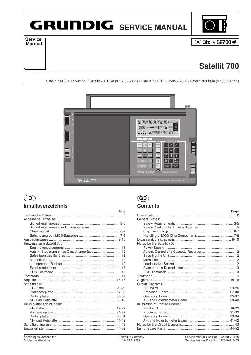
Grundig Satellit 700 Service Manual

This is the 40 pages manual for Grundig Satellit 700 Service Manual.
Read or download the pdf for free. If you want to contribute, please mail your pdfs to info@audioservicemanuals.com.

Page: 1 / 40
left right
Grundig Satellit 700 Service Manual

Extracted text from Grundig Satellit 700 Service Manual (Ocr-read)


Page 1

G RU n DIG SERVICE MANUAL

Service
Manual

® th * 32700 #

Satellit 700

Satellit 700 (9.15055-8151) / Satellit 700 USA (9.15055-7151i/Satellit 700 GB (915055-6251) / Satellit 700 ltalia (9.15055-6151)

SATELLIT7oo

®

lnhaltsverzeichnis
Seite
Technische Daten ........................................................................... 2
Allgemeine Hinweise
Sicherheitshinweise
Sicherheitshinweise zu LItthmbatterIen
Chip- -Teohnik ..............
Behandiung von MOS- Bauteiien.
Ausbauhinweise ............................................................... 9-10
Hinweise zum Satellit 700
Spannungsversorgung ...................
Autom. Steuerung eines Cassettengerate
Befestigen des Gerates.
Memofiles
Lautsprecher-Buchse .
Synchrondetektor
FiDS-Testmode
Testmode
Abgleich
Schaltbiider:
HF-Platte ......
Prozessorplatte
Bedienplatte .t
NF- und Potiplatte...
Druckplattenabbildungen

HF-Platte 19-22
Prozessorplatte 31-32
Bedienplatte .. 33-34

NF- und Potiplatte
Schaltbildhinweise
Ersatzteiiliste

Efiflfimflfifl

u: um Momma

magma

WW

WWW
on

WORLD RECEiVER fiABinnAYA 5mm

Emumzmzummnizs mmmu

Contents
Page
Specification .................................................................................... 2
General Notes:
Safety Requirements
Safety Cautions for Litthm BatterIes
Chip Technology ...........................
Handling of MOS Chip Components
Disassembiy instructions ........................................................... 9-10
Notes for the Satellit 700:
Power Supply ......................................
Autom. Control of a Cassette Fiecorde
Securing the Unit
Memofiles
Loudspeaker Socket .
Synchronous Demoduiator .
RDS-Testmode
Testmode
Alignment
Circuit Diagrams:
RF Board .......
Processor Board
Operating Board
AF- and Potentiometer Board ............................................ 38-40
Illustration of Printed Board '
RF Board
Processor Board
Operating Board
AF- and Potentiometer Board
Notes for the Circuit Diagram .
List of Spare Parts 44-52

Anderungen vorbehaiten
Subjeci to alteration

Printed in Germany
VK 225 1291

Service Manual Sacthr. 7201071955
Service Manual Part No. 7201071965

Page 2

J

Sate/Iii 700

Technische Daten / Specification

Technische Daten

Spannungsversorgung

- Durch Batterien:
4x 1 ,5 V-Monozellen (IEC LR20) oder4 x handelflbliche 4 Ah-Akkus
in gleicher GroBe (IEC KFI 35/62).
Eingebaute, sich automatisch wiederaufladende Lithiumbatterie iUr
Datensicherung.

- Externe Versorgung: NetZteil NR 90 oder Gleichspannung 9-12 V:

Ausgangsleistung (Mono und Stereo) an 7,552

- NetZ-/Musikleistung nach DIN 45324: 1 bzw. 2 x 1,5W

- Spitzenleisung: 1 bzw. 2 x 3W

- Sinusleistung bei Batteriebetrieb nach DIN 45324: 1 bzw. 2 x 0,5W

Batterie~Betriebsstunden (gemessen nach DIN 45314)
Typ IEC LFI 20 (Alkali-Mangan)

z.B. VARTA energy 2000 ALKALINE: ca. 90 Std.

z.B. Duracell MN 1300: ca. 110 Std.

4 Ah-Accus (IEC KR 35/62): ca. 25 Std.

Eingebaute Antennen
- Teleskopantenne fLir UKW und Kurzwelle, Ferritstab-Antenne for
MW und LW

AnschluBbuchsen

- zum Ansteuern von Verstarkeranlagen und fiJr Mono- und Stereo-
Uberspielungen (Aufnahmen); LINE OUT (Cinch-Buchsen)

- fflr Kopfhorer mit 3,5-mm-Klinkenstecker; 32-20009

- fflrAuBenlautsprecher(linkerundrechterKanal)mit3,5-mm-Klinken-
stecker; SQ

- zum Steuern externer Gerate, z.B. Bandgerate (Schaltausgangs-
Buchse) potentialfreie Flelaisansteuerung

- fUr externe Spannungsversorgung; NetZteil NFI 90 oder Gleich-
spannung 9-12V (5,5mm-Koaxial-Buchse)

- fUrAu Benantenne DIN 45325 (FM 759/AM 5OQ-KoaxiaI-Buchse fiJr
alle Bereiche)

Emptangsbereiche
FM: 875 -108 MHZ
SW: 1612 - 30000 kHZ
3950 - 26100 kHz (Satellit Italia)
MW:528 - 1611 kHZ
LW: 150 - 353 kHz
150 - 302 kHz (Saiellit Italia)

Emplangbare KW-Bénder

Band FrequenZ (kHz)

160-m-Amateur 1815 - 1890 (nicht bei Satellit Italia)
120-m-Rundlunk 2300 - 2498 (nicht bei Satellit Italia)
90-m-Tropen 3200 - 3400 (nicht bei Satellit Italia)
80-m-Amateur 3500 - 3800 (nicht bei Satellit Italia)

75-m-Flundfunk 3900 - 4000
60-m-Tropen 4750 - 5060
49-m-Rundfunk 5950 - 6200
41 -m-Flundfunk 7100 - 7300
40-m-Amateur 7000 - 7099
31 -m-Rundfunk 9500 - 9900

10100 - 10150
11650 - 12050
13600 - 13800
14000 - 14350
15100 - 15600
18065 - 18170
17550 - 17900
21000 - 21449
21450 - 21850
24890 - 24990
25650 - 26100
28000 - 29700 (nicht bei Satellit Italia)

30-m-Amateur
25-m-Flundfunk
22-m-Rundfunk
20-m-Amateur
19-m-Flundfunk
17-m-Amateur
16-m-Flundfunk
15-m-Amateur
13-m-Rundfunk
12-m-Amateur
11-m-Flundfunk
10-m-Amateur

ZF:
FM = 10,7 MHZ
AM: ZF 1 = 545 MHZ, ZF 2 = 450 kHz

Specification

Power supply requirement
- From batteries:
4 x 1.5 V"HP 2" (IEC LR20) or 4 commercially available 4 Ah
accumulators of the same size (IEC KR 35/62).
Built-in automatically recharging lithium battery for data protection.
- From external voltage supply: Mains unit NR 90 or 9-12 V DC.

Output power (Mono and Stereo) in 7.59

- Mains/music power according to DIN 45324: 1 and 2 x 1,5W, resp.

- Peak power: 1 and 2 x 3W, resp.

- Sinus power on battery operation acc.to DIN 45324: t and 2 x 0,5W,
resp.

Batterie working hours (measured according to DIN 45314)
Typ IEC LR 20 (Alkali-Mangan)

e.g. VARTA energy 2000 ALKALINE: ca. 90 hours.

e.g. Duracell MN 1300: ca. 110 hours.

4 Ah-Accus (IEC KR 35/62): ca. 25 hours.

Built-in aerials
- Telescopic aerial for FM and SW, ferrite rod aerial for MW and LW.

Connecting sockets for

- driving amplifier systems and for mono and stereo tape recordings;
LINE OUT (phono sockets)

- headphone with 3.5mm jack plug; 32-20009

- external loudspeaker (left-hand and right-hand channel) with 3.5mm
jack plug; 851

- driving external units, e.g., tape recorders (output switch jack);
potential-free relay control

- external power supply; mains unit NR 90 or 9-12V DC (5.5mm
coaxial socket)

- external aerial DIN 45325 (FM 759/AM 509 coaxial socket for all
wavebands).

Wavebands
FM: 87.5 - 108 MHZ
SW: 1612 - 30000 kHZ
3950 - 26100 kHz (Satellit Italia)
MW:528 - 1611 kHz
LW: 150 - 353 kHZ
150 - 302 kHz (Satellit Italia)

Receivable SW Bands
Band Frequency (kHz)
160-m-amateur 1815 - 1890 (not on Satellit Italia)

120-m-radio 2300 - 2498 (not on Satellit Italia)
90-m-tropic 3200 - 3400 (not on Satellit Italia)
80-m-amateur 3500 - 3800 (not on Satellit Italia)
75-m-radio 3900 - 4000

60-m-tropic 4750 - 5060

49-m-radio 5950 - 6200

41 -m-radio 7100 - 7300

40-m-amateur 7000 - 7099

31 -m-radio 9500 - 9900

30-m-amateur 10100 - 10150

25-m-radio 11650 - 12050

22-m-radio 13600 - 13800

20-m-amateur 14000 - 14350

19-m-radio 15100 - 15600

17-m-amateur 18065 - 18170

16-m-radio 17550 - 17900

15-m-amateur 21000 - 21449

13-m-radio 21450 - 21850

12-m-amateur 24890 - 24990

11-m-radio 25650 - 26100

10-m-amateur 28000 - 29700 (not on Satellit Italia)
IF:

FM = 10,7 MHz

AM: IF 1 = 54,5 MHZ, IF 2 = 450 kHz

GRUNDIG Service-chhnik