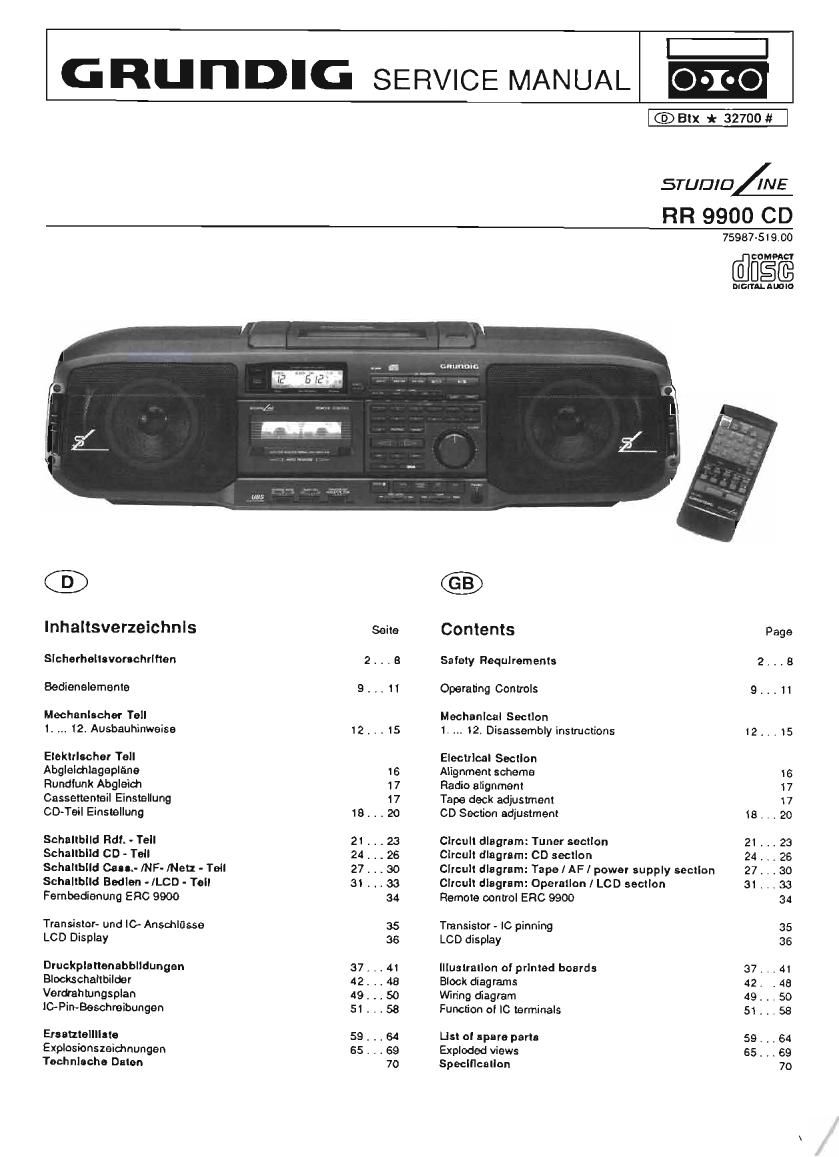
Grundig RR 9000 CD Service Manual

This is the 44 pages manual for Grundig RR 9000 CD Service Manual.
Read or download the pdf for free. If you want to contribute, please mail your pdfs to info@audioservicemanuals.com.

Page: 1 / 44
left right
Grundig RR 9000 CD Service Manual

Extracted text from Grundig RR 9000 CD Service Manual (Ocr-read)


Page 1

GRUI'IDIG SERVICE MANUAL

I:|

CED BIX * 32700 #

STUDIO 4 [NE

RR 9900 CD

75987-519130
comma

[dam

mcrrAL nmlo

cn-mmr.

®

Inhaltsverzeichnls
Sicherheilsvonchrlhan
Sedienalemanle

Mechanlnchar Tell
I. 12. Ausbauhinweise

ElekIrlscher Tell
Abglelchlagepléne
Rundfunk Abglaid'l
Cassenenlail Enstallung
CD-Teil Einsvellung

Schallblld Rdf. - Tell

Schallblld CD - Tell

Schnlibild Cetus fNF- [Nell - Tell
Schnllbild Bedlan -/LCD - Tell
Fembedanung ERC 9900

Transislor- und It} Ansdmlflsse
LCD Display

Druckplanenabblldungen
Blocks challbilder

Verdrah tungsplan

l0- Pin-Beschmibungen

Ersaulellllnle
Explosionszeidmungen
Tachnloeho Dale»

12.

18...

21...
24...
27...
3t...

37...
42...
49...

59...
ES...

Selle

.11

Contents Page
Salely Requirements 2. . . B
Operanng Controls 9. . . 11

Mechanical Sacllon
1. 12. Disassembly instructions I2 . . . 15

Eleclrlcal Section

Alignment scheme 16
Radio alignment $7
Tape deck adjustmenl l 7
CD Section adjustment is . . . 20
Clrcull diagram: Tuner section 21 . . . 23
Clrcull dlagrlrn: CD secllon 24 . . . 26
Circuit diagram: Tape I AFI power supply section 27. . .30
circull diagram: Operallan I LCD socllon 31 . . . 33
Ramole Don Irol ERC 9900 34
Transistor - IC pinning 35
LCD display 36
Iliualrallon oi prlntad boards 37 . , . 41
Block diagrams 42. . 45
Wiring diagram 49. . , 50
Function 0! Ic terminals 51 . . , 58
U5! ol spare part. 59. . . 64
Exploded views 65. . . 69

Specificallon 7O

Page 2

Sicherheitsvorschriften / Safety requirements / Prescriptions de sécurité / Prescrizioni
de sicurezza/ Prescripciones de seguridad

Achtung: Bel Erngrrllen Ins Gerét sind die Slcherheitsvor-
schrilten naoh VDE 701 (reparaturbezogen) bzw VDE 0860
I IEC 65 (geratebezogen) zu beachten!

Bautetle nach IEC- bzw. VDE-Richtlrnien ' lm Ersatzlall nur
A Terle mlt glelcher Spezilrkation verwendenl

MOS - Vorschrilten berm Umgang mil MOS , Bauteilen be-
achten!

Attenrton: Please observe the applicable salary requrre-
ments according to VDE 701 (concerning repairs) and VDE
0360/ ISO 65 (ooncernrng type 0! product)!

Components to IEC or VDE guidelines! Only use compo-

A ! 3 A nents With the same specifications lor replacement!
Observe MOS components handling Instructions when ser-
vrcrng!

Attention: Priere dobserver les prescrtpltons do sccunte
VDE 7D\ (ooncernantles reparations) et VDE OSSOIIEC 65
(concernant le type do produit)l

i A Composants réponoant aux normes VDE or: IE0 Les remA
I placer unrquement par des oomposants ayant Ies memes
specllrcattons.

Lors de la manipulation des circuits MOS, respecter les
Descriptions MOS!

Altenzlone; Osservarne Ia oorrtspondenti orescriztonr dl
srcurezza VDE 70l (concernenle servtziol e VDE 0860 / IEC
65 (concernente il ripe di prodotlo)!

Componenti secondo Ie norme VDE rrsp le IEC! In caso dr
sostiruzrone tmpiegam solo componenu con la slesse carati
teristiche

AA

Osservare Ie relatrve prescrrzrom durante, lavorr oon oom-
ponenti M05!

Alenciou: Racomendamos las normas de segurrdad VDE
u olras normas equivalentes. pot elemplo. VDE 70l para re»
paracrones, VDE 0860 I IEC 65 para aparatos'

6)
AA

Componentes que cumplen las normas VDE/IEC, En caso
de sustllucion emplear oomponentes con idénucas especri
lrcaciones!

Durante la reparacion observar las normas sobre com-
punentes MOS'

U.S.&
Canada

AA

Attention. This set can only be operated lrom AC marns ol
l20 V/60 Hz Also observe the information given on the rear
ol the set

CAUTION-tor continued protection against risk 0! fire ref
place only with same type oi lusas'

CAUTION: to reduce the risk ol electric shock. do not re-
move cover (or back). no userserviceable parts inside.
reler servicing to quflitied service personnel
Components to salary guidelines (IECIUL,)| Only use com
ponents with the same specifications (or replacement!
Observe by checking leakage-current or Ieststance measu-
rement that the exposed parts are acceptably insulated
from the supply circuit,

Observe MOS components handling instructions when ser-
vrcing!

AA

® Sicherheitsbesllmmungen Saiety Standard Compliance

© Disposiciones para la Seguridad Salety Instructions

© Norma di Sicurezza

Slcherheitsoeslirnmungen

Nach Servicearbeiten ist bei Geralen der Schutzklasse ll die Mes-
sung des Isolationswiderstandcs und des Ableitsrromes bet ernge-
schalletem Gerat nach VDE 0701 I Tell 200 MW. der am Aulstellort
geltenden Vorschrrh. durchzuluhren!

Dreses Gerat entspricht der Schutzklasso ll, erkennbar durch das
Symbol @

o Messen des lsolatlonswidarstandes nach VDE 0701.
lsolatronsmesser (U 135 : 500 V7) glerchzeitig an beiden Netzpo-
len und zwrschen allen Gehauser ode! Funktronstetlen (Antenna,
Bucltscn. Tastenl Zlenerlen, Schrauben usw ) aus Metall oder
Motallegierungen anlegen Fehlerlrer lsl das Gerét bei emem

R 50, 2 2 Mn bet U m, = 500 V»

MeBxerti 2 l s (Fig ll
Anmerkung: Ber Geraten der Schutzklasse ll kann durch Entlar
dungswrderstande der Melswerl des Isolationsmderslandes kon»
struktionsbedrngt < 2 Ma sein, In diesen Fallen rst die Ableltstrom-
messung mafigebend

Prulling \
Test item '
Apparecchio lrl mlsura
Piece 6 essai

Aparato de prueba

-m

uEI'RAlEstEn)

Neusrecker des Prullings <~

Mains plug 01 test Item

Spine di rete dell'apparecchro tn nusura
Fiche secteur piece dc essat

-39

JAN

® Prescriptions de Sécurllé

o Messen des Ablellstrornes nach VDE 0701.
Ablerrstrornrnesser (U m, : 220 V:) gleichzertrg an harden Netz-
polen und zwrschen allen Gehause-oder Funktionsteilen (Amen,
ne Buchsen. Tasten Zierteilen Schrauben, usw) aus Melall
oder Metallegierungen anlegen Fehlerirei ist das Gerat hei
einem.

lAbleIr S '"A [5' U Tosl
Meflzeit. 2 l s (Fig. 2)

0 WI! empiehlen die Messungen mtl Clem METRATESTEFI 3
durchzuluhren (Meflgerét zur Prolung elektrrscher Gerate nach
VDE 0701)

Melrawan GmbH
Geschallsstelle Bayern
Triebstr 44

D 8000 Mirnclten 50

O ist die Slcherhert des Gerales nrcht gegeben. well
- etne Instandsetzung unmoglich isl
- oder der Wunsch des Benutzers besteht dre lnstandsetzung

nrcht durchluhren zu lassen. so mufl dem Belrerbcr drc vom
Gerét ausgehende Gelahr sohnitlich mrtgeleilt warden,

= 220 V:

, r MIt der Grellklemme alle Metallteile u metallrsrenen Tetle aprnsten
7 All metal and metallic parts must be tested wrth the Caliper clamp
Can cavo orovvrsro dr morsetto tocmre intro 19 partl metalime a
melalllzzale
A larde d'une plnce vénlter routes les oantos metalquues ou
metallisees,
Con la plnza. tocar todas las ptezas merollcas o metalrzadas

NeusledlEr/Malns plug/Spina di vets/Fiche secleurlclavrla de red

Claviia 69 red del aparzrto de pmeba
Prullmg \
Test item \\
Apoareochio in mtsura
Piece d 'essai
Aparato de orueba

Fig. l

@ mA-Q

MURAYEern 3

Fig 2

\

Net: Sled(er des Prunings - -
Mains plug oi test llem

Spina di were dollapparocchro l" mlsula
Fiche secteur piece de essar

Clavlia de ted del aparalo do prueba

z

/

flMitder Greilklemme alle Melallteile u metallisierlen Terle abrasten
All metal and metallic parts must be tested with lite Caliper clamp,
Con cavo prowrsto dl morsetto rowan; rutre le parti metallrme o
metallrzzare
A lalde dune prnce vérilier loutes les parties metallloues ou
metallrsees

Con la prnza. romr todas Irrs prams melalrcas o metallzadas

-Netzstecker/Mams plug/Sptna oi rate/Fiche secteui/Clavya dc- led