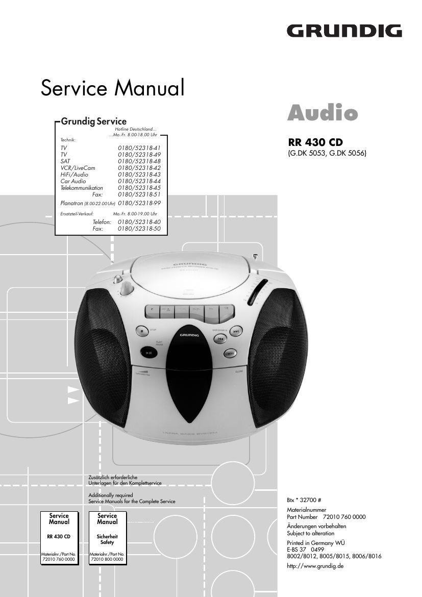
Grundig RR 430 CD Service Manual

This is the 20 pages manual for Grundig RR 430 CD Service Manual.
Read or download the pdf for free. If you want to contribute, please mail your pdfs to info@audioservicemanuals.com.

Page: 1 / 20
left right
Grundig RR 430 CD Service Manual

Extracted text from Grundig RR 430 CD Service Manual (Ocr-read)


Page 1

Es gelten die Vorschriften und Sicherheitshin- weise gemŠ§ dem Service Manual "Sicherheit", Materialnummer 72010 800 0000, sowie zusŠtz- lich die eventuell abweichenden, landes- spezifischen Vorschriften!The regulations and safety instructions shall be valid as provided by the "Safety" Service Manual, part number 72010 800 0000, as well as the respective national deviations. 1 - 2 GRUNDIG Service Allgemeiner Teil / General Section RR 430 CD Table of Contents Page General Section .............................. 1 - 2 É 1 - 6 Test Equipment ........................................................................\ .. 1 - 2 Service Hints ........................................................................\ ...... 1 - 3 Technical Data ........................................................................\ ... 1 - 3 Operating Hints ........................................................................\ .. 1 - 4 Disassembly Instructions ........................................................... 1 - 5 Adjustment Procedures .................. 2 - 2 ... 2 - 3 Layout of the PCBs and Circuit Diagrams ................... 3 - 1 É 3 - 14 Block Diagram ........................................................................\ .... 3 - 1 IC Block Diagram ....................................................................... 3 - 1 Wiring Diagram ........................................................................\ .. 3 - 2 Layout of the PCBs: Main PCB (Tuner, CD, Amplifier Parts) .................................. 3 - 4 Stereo Switch PCB ................................................................. 3 - 4 Volume PCB ........................................................................\ .... 3 - 4 LED PCB ........................................................................\ ........ 3 - 5 Haedphone Socket PCB ........................................................ 3 - 5 Function PCB ........................................................................\ . 3 - 6 Tape PCB ........................................................................\ ....... 3 - 6 Battery Contact PCBs ............................................................... 3 - 7 Power Supply PCB .................................................................. 3 - 7 Circuit Diagrams: Tuner (Main PCB) .................................................................. 3 - 8 Amplifier Part (Main PCB) ...................................................... 3 - 8 Power Supply ........................................................................\ . 3 - 9 CD Part (Main PCB) ............................................................. 3 - 10 Tape Part ........................................................................\ ..... 3 - 12 Function PCB ....................................................................... 3 - 14 Exploded View and Spare Parts List .............................. 4 - 1 É 4 - 3 Inhaltsverzeichnis Seite Allgemeiner Teil ............................. 1 - 2 É 1 - 6 Me§gerŠte ........................................................................\ .......... 1 - 2 Service-Hinweise ....................................................................... 1 - 3 Technische Daten ...................................................................... 1 - 3 Bedienhinweise ........................................................................\ .. 1 - 4 Ausbauhinweise ........................................................................\ . 1 - 5 Abgleichvorschriften ...................... 2 - 1 ... 2 - 2 Platinenabbildungen und SchaltplŠne ........................... 3 - 1 É 3 - 14 Blockschaltplan ........................................................................\ .. 3 - 1 IC-InnenschaltplŠne ................................................................... 3 - 1 Verdrahtungsplan ....................................................................... 3 - 2 Platinenabbildungen:Hauptplatte (Tuner-, CD-, VerstŠrkerteil) ............................... 3 - 4 Stereoschalterplatte ............................................................... 3 - 4 Volume-Platte ........................................................................\ .. 3 - 4 LED-Platte ........................................................................\ ...... 3 - 5 Kopfhšrerbuchsenplatte ......................................................... 3 - 5 Funktionsplatte ....................................................................... 3 - 6 Cassettenplatte ...................................................................... 3 - 6 Batteriekontaktplatten ............................................................... 3 - 7 Netzteilplatte ........................................................................\ .... 3 - 7 SchaltplŠne: Tunerteil (Hauptplatte) ........................................................... 3 - 8 VerstŠrkerteil (Hauptplatte) .................................................... 3 - 8 Netzteil ........................................................................\ ........... 3 - 9 CD-Teil (Hauptplatte) ........................................................... 3 - 10 Cassettenteil ........................................................................\ 3 - 12 Funktionsplatte ..................................................................... 3 - 14 Explosionszeichnung und Ersatzteilliste .................................. 4 - 1 É 4 - 3 Allgemeiner Teil Me§gerŠte Me§sender, Wobbelsender, Oszilloskop, FrequenzzŠhler, NF-Voltme- ter, Tonhšhenschwankungsmesser, DC-Voltmeter. Beachten Sie bitte das GRUNDIG Me§technik-Programm, das Sie unter folgender Adresse erhalten: General Section Test Equipment Signal Generator, Sweep Generator, Oscilloscope, Frequency Coun- ter, AF Voltmeter, Wow and FlutterMeter, DC Voltmeter Please note the GRUNDIG Catalog "Test and Measuring Equipment" obtainable from: Grundig AG GeschŠftsbereich Instruments Test- und Me§systeme WŸrzburger Str. 150D-90766 FŸrth Tel.: 0911 / 703-4118, Fax: 0911 / 703-4130 eMail: instruments@grundig.de Internet: http://www.grundig-instruments.de

Page 2

GRUNDIG Service1 - 3 Allgemeiner Teil / General Section RR 430 CD Technische Daten Spannungsversorgung: Netzbetrieb ............................................................... 230V, 50/60Hz Batteriebetrieb ................................................. 8 x 1,5V (R20, UM1) VerstŠrkerteil: Ausgangsleistung (DIN 45324, 10% THD): Musikleistung ................................................................ 2 x 3200mW Sinusleistung ................................................................. 2 x 1600mW Stereo-Kopfhšrer-Klinkenbuchse ........................................ 3,5mm ¿ Rundfunkteil: Wellenbereiche ................................................... FM 87,5 Ð 108MHz MW 526,5 Ð 1606,5kHzLW 148,5 Ð 283,5kHz Antennen .................................................... Teleskopantenne fŸr FM eingebaute Ferritstab-Antenne fŸr MW/LW Cassettenteil: TontrŠger .................................. Compact-Cassette nach DIN 45516 Spurlage ....................................................... Viertelspur international Bandgeschwindigkeit ..................................................... 4,76cm/sec. Motor ..................................................................... Gleichstrommotor FrequenzŸbertragungsbereich .................................. 125Hz Ð 10kHz GerŠuschspannungsabstand ................................................. ³ 42dB Gleichlauffehler .................................................................... £ 0,25% Automatik ............................ Aussteuerungsautomatik bei Aufnahme Automatisches Auslšsen der Tasten am Bandende CD-Teil: FrequenzŸbertragungsbereich .................................... 20Hz Ð 20kHz GerŠuschspannungsabstand ................................................... 65dB Technical Data Power Supply: Mains operation ........................................................ 230V, 50/60Hz Battery operation ............................................. 8 x 1.5V (R20, UM1) Amplifier Section: Output power (DIN 45324, 10% THD): Music power ................................................................. 2 x 3200mW Nominal power .............................................................. 2 x 1600mW Jack socket for stereo headphones ................................... 3.5mm ¿ Radio Section: Waveband ........................................................... FM 87.5 Ð 108MHz MW 526,5 Ð 1606,5kHzLW 148,5 Ð 283,5kHz Aerials ......................................................... Telescopic aerial for FM Built in ferrite rod aerial for MW/LW Cassette Section: Cassette ........................................ Compact cassette to DIN 45516 Track System ............................................ International quartertrack Tape Speed ................................................................... 4.76cm/sec. Motor ........................................................................\ .......... DC motor Frequency Range ..................................................... 125Hz Ð 10kHz S/N Ratio (weighted) ............................................................. ³ 42dB Wow and Flutter .................................................................. £ 0.25% Automatic ..................................... Automatic recording level control Automatic button release at tape end CD Section: Frequency range ........................................................ 20Hz Ð 20kHz S/N ratio, weighted .................................................................. 65dB Service-Hinweise Cassettenteil -berprŸfen Sie vor Beginn der Service-Arbeiten, ob die Magnetkš\ pfe, die Tonwelle und die Gummiandruckrolle frei von Bandabrieb sind. Zum Reinigen dieser Teile verwenden Sie ein mit Spiritus oder Reini- gungsbenzin getrŠnktes WattestŠbchen; dadurch verbessert sich der Aufnahme- und Wiedergabepegel, sowie der Bandlauf. Nach dem Ersatz von Magnetkšpfen oder sonstiger Bauteile mŸssen die technischen Daten des GerŠtes anhand der im Service Manual vorgegebenen Me§werte ŸberprŸft bzw. eingestellt werden. CD-Teil Bei Ausbau der CD-Lasereinheit mu§ vor Abziehen der Steck- verbindungen eine Schutzlštstelle (Kurzschlu§) auf der Leiterpla\ tte der Lasereinheit angebracht werden, um eine Zerstšrung der Laser- diode durch statische Aufladung zu vermeiden. Beim Einbau einer neuen Lasereinheit (CD-Laufwerk) mu§ nach Einstecken der Steckverbinder die werkseitig angebrachte Schutzlštstelle entfernt werden! Service Hints Cassette Section Before commencing service work, ensure that the magnetic heads, the capstan and the pinch roller are free from particles produced by tape abrasion. The recording and playback levels and the tape run can be improved by cleaning these parts with a cotton-wool tip soaked in spirit\ or cleaning benzine. If the heads or other components have been replaced, the technical data of the recorder must be checked or adjusted according to the values specified in the Service Manual. CD Section When removing the Laser pick-up, the Laser pick-up PCB must be provided with a protective soldered joint (short circuit) before unplu\ g- ging the connectors to avoid damage to the Laser diode by static charges. When inserting the new Laser pick-up (CD drive mechanism) the soldered joint fitted at the factory must be removed after the connectors are plugged in. kurzschlie§en short circuit