Grundig RR 340 Service Manual

This is the 7 pages manual for Grundig RR 340 Service Manual.
Read or download the pdf for free. If you want to contribute, please upload pdfs to audioservicemanuals.wetransfer.com.

Page: 1 / 7
Grundig RR 340 Service Manual

Extracted text from Grundig RR 340 Service Manual (Ocr-read)


Page 1

RR 340 / RR 340 L
RR 340 A/RR 340 AL

1. Allgemeines

Die Zahlen im Text und bei den Abbildungen sind mit den
Positionsnummern der Ersatzteilliste identisch. Teile - die in der
Ersatzteilliste nicht vorkommen - sind mit Buchstaben gekenn-
zeichnet, Nicht abgebildete Positionen finden Sie in derErsatzteil-
Iiste.

lst es erforderlich, lackgesicherte Schrauben zu losen, mussen
diese nach AbschluB der Reparatur wieder verlackt werden.
SaubereGummilaufllachen tragen wesentlich zurBetriebssicher-
heit der Mechanik bei, diese sind mil Relnigungsmlttel (T estben-
zin) zu reinigen. Miissen Klebestellen emeuert werden, so ist bei
Polystyrol auf Polystyrol Methylenchlorid oder Benzcl, bei Poly-
styrol auf Metall Haftkleber (A 208 Fa. Akemi) zu verwenden.
Magnetische Werkzeuge durien nicht in die Nahe des Magnet-
kopfes gebracht werden.

Vor Service-Arbeiten uberprufen Sie bitte, ob die Tonwelle, die
Gummiandruckrolle, sowie der Magnetkopf frei von Bandabrieb-
riickstanden sindt Zum Reinigen dieser Teile eignet sich ein spiri-
tus»oder reinigungsbenzingetranktes Wattestabchen,

Nach jederReparatur am Laufwerk sind die Kopfe115,116, dieTon<
welle sowie die Andruckrolle mit Spiritus Oder Reinigungsbenzin
zu reinigen.

2. Riickwand abnehmen
- 5 Schrauben herausdrehen und Rflckwand abnehmen.

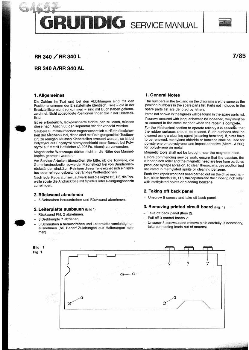
3. Leiterplatte ausbauen (Bild 1)

- Rdckwand Pkt. 2 abnehmen.

- 3 Drehknopfe 7 abziehen,

~ 3 Schrauben a herausdrehen und Lelterplatte vorsichtig her-
ausnehrnen (bei Bedari Zuleitungen aus Halterungen neh-
men).

7/85

1. General Notes

The numbers in the text and on the diagrams are the same as the
position numbers in the spare parts list. Parts not included in the
spare parts list are denoted by letters.

items not shown in the figures will be found in the spare partslist.
if screws secured with lacquer have to be loosened, they must be
re-secured in the same manner when the repair is com [eta
For the Mechanical section to operate reliably it is essen rat that
the rubber surfaces should be cleaned. Such surfaces shall be
cleaned using a cleaning agent (cleaning benzene) It joints have
to be renewed, methylene chloride or benzene shall be used for
polystyrene on polystyrene, and impact adhesive (Akemi. A 206)
for polystyrene on metal.

Magnetic tools shall not be brought near the magnetic head.
Before commencing service work, ensure that the capstan, the
rubber pinch roller and the magnetic head are free from particles
produced by tape abrasion. To clean these parts, use a cotton bud
saturated in methylated spirits or cleaning benzene.

Each time repair work has been carried out on the drive mechan-
ism, clean heads 1 15, 116,the capstan and the rubber pinch roller
with methylated spirits or cleaning benzene.

2. Taking off back panel
- Unscrew 5 screws and take off back panel.

3. Removing printed circuit board (Fig. 1).

- Take off back panel (item 2).

- Pull off 3 control knobs 7.

- Unscrew 3 screws a and remove p.c.b carefully (if necessary,
take connecting leads out of mounts).

Page 2

aesifickungswiw LOSCHKOPF MIC LINKS MIC. RECHTS , 4m; ANTENNE


COMPONENT SIDE ERASE HEAD MICV LEFT MIC. RIGHT F, 56:10 AM ANT. COIL m4
FM
.,
RR 340 L i??? W
I W
é&
a f:
a; Lu
g_ I:L
0; 3
P: 8
1 _J


STEREO
LED
J.
TUNING
2% LED
<\ I
.
BATTERIE 220V~ A/W-KOPF LEAF
BATTERY RIP HEAD SW
Bestiickungsseite
COMPONENT SIDE LOSCHKOPF > 5 MIC. LINKS MIC, RECHTS ANTENNE
RR 340 ERASE HEAD MIC. LEFT MIC. RIGHT AM ANT. con.
fig
Er} §
K Lu
1 CL
:0 U)
l- D
I) D
S. 3 Tea
STEREO
J. LED
TUNING
LED

BATTERIE MOTOR LEAF SW A/W-KOPF
BATTERY 220V~ 1 RIP HEAD