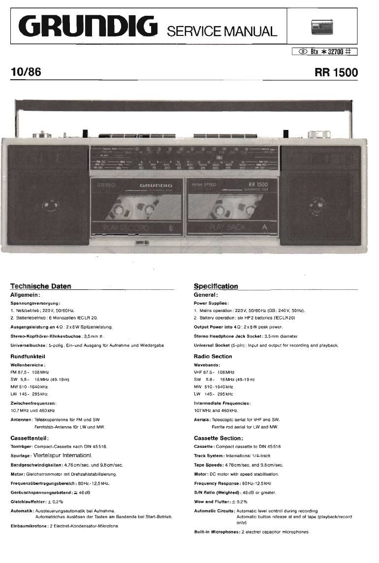
Grundig RR 1500 Service Manual

This is the 7 pages manual for Grundig RR 1500 Service Manual.
Read or download the pdf for free. If you want to contribute, please mail your pdfs to info@audioservicemanuals.com.

Page: 1 / 7
left right
Grundig RR 1500 Service Manual

Extracted text from Grundig RR 1500 Service Manual (Ocr-read)


Page 2

Die Zahien im Text und bei den Aboildungen sind identisch mlt den Posi-
tionsnummem der Ersatzteilliste.

lst es eriorderllch, Iaclgqesicherte Schrauben zu losen, mussen olese
nach Abschlufl der Reparalur wieder verlackt werden.

Vor Service-Amelten ist ZU OberDeren. 00 die Tonwetlen, die Andruckrol-
ten. sowie die Magnetkopte lrei von Bandabriebrficksttfinden sind. Zum
Relnlgen dieser Telle eignet slch ein mit Spiritus oder Reinigungsbenzin
getrénktes Wattestfibchen.

Gehéuseflordeneii abnehmen

Batterietachdeckel 14 abnehmen und 5 Schrauben herausdrehen.
Drehknooie 6, 7 und 5 abziehen.
Schrauhe o (unter Drehknopl B) herausdrehen.

Cassetteniachdeckel 3 und 4 offnen und Gehause»\lorderteil1 aoneh-
men.

Leiterplatten ausbauen

The numbers in the text and figures are identical with the item numbers in
the spare parts lists.

It screws secured with lacquer have to be loosened they must be re-se-
cured in the same manner when repair works are finished.

Before commencing repairworks make sure that the capstan. the rubber
pinch roller and the magnetic head are free from particles produced by
tape abrasion. To clean these parts use a stick with a cotton-wool tip
soaked with spirit or cleaning benzene.

Removing the Cabinet Front

Remove the battery compartment cover 14 and unscrew five screws.
Pull oft the control knobs 6. 7 and 8.

Undo screw 0 (below control knob 8).

Open the cassette compartment lid 3 and 4 and remove the cabinet
from 1,

Removing the Printed Circuit Boards

o TUNER P.C.B

Ausbau der Laufwarke

Gehause-Vorderteil 1 abnehmen.

B Schrauben a und 2 Schmuben h hemusdrehen

LED-Blende g nach rechts schieben und nach unten wegnehmen.
Die Laufwerke unten (Motoren) anheben und vorsichtig herausneh-
men.

Beim Einbau von Lauiwerk B darauf achten, deli der Autnahrne Schalv
ter in den Mitnehmer elngreitt.

Motor nusbauen

Lauiwerk ausbauen.

2 Sehrauben c herausdrehen.

Riemen 63 und bel Laufwerk B Zéhlwerkriernen 33 aushaingent
Lagerplatte A mit Motor 68 abnehmen.

2 Schrauben 66 herausdrehen (Lage oes Motors heachten) und Motor
68 abnehmen.

Removing the Drive Mechanisms

Remove the cabinet iront 1.

Unscrew eight screws 3 and two screws t2.

Push the LED mask g to the right and remove it in downward direction.
Lift the drive mechanisms at the bottom (motors) and take them out ca-
reiully,

When mounting drive mechanism B make sure that the record switch
engages with the driver.

Removing the Motor

Dismount the drive mechanism.

Undo two screws c.

Unhooklhe belles andthe bett 33 otthe counteroidrlve mechanism B.
Remove the bearing plate A with the motor 88.

Undo two screws 66 (note the position of the motor) and remove the
motor 68.

Schwungmd ausba uen

Latrfwerk ausbauen
2 Schrauben c herausdrehen,
Riemen 63 und bei Lauiwerk B Zahlwerkriemen 33 aushangen

Lagernlatte A mit Motor 68 abnehmen. Scheibe e abnehmen, unu
Schwungrad 64 herausziehen.

Beim Embau Scheibe e erneuem

Removing the Flywheel

Dismount the drive mechanism
Unou two screws 0.
Unhook the belt 83 and the belt33 otthe counter oidrive mechanism B.

Remove the bearing plate A with the motor SB. then the disk 2 and
take out the ilywheel,

Use a new disk 2 when reassembling.