Grundig Record boy 1100 Service Manual

This is the 8 pages manual for Grundig Record boy 1100 Service Manual.
Read or download the pdf for free. If you want to contribute, please mail your pdfs to info@audioservicemanuals.com.

Page: 1 / 8
left right
Grundig Record boy 1100 Service Manual

Extracted text from Grundig Record boy 1100 Service Manual (Ocr-read)


Page 2

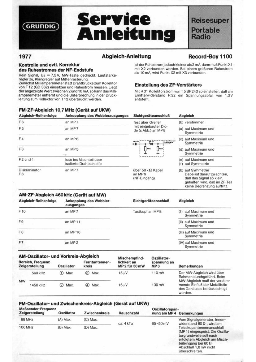
Alignment Instructions

Adjusting the audio output stage

and quiescent current

No signal. Us (battery voltage) - 7.5V. Mw-button de-
pressed. volume control at minimum, tone control to centre.
Remove the wire link in the collector circuit of T 12 (GD 362)

and insert a milliamp-meter to measure the quiescent current.

It the reading is between 2 and 10mA. the milllamp-meter
can be disconnected and the wire llnk replaced to complete

FM-IF-Ailgnment 10.7 MHz (switch to VHF)

the collector circuit of T 12.

But if the quiescent current is less than 2 mA. point X1 must
be connected with point X 2. If the quiescent current is more
than 10 mA. point X 2 must be connected with point X 3.

Adjusting the IF amplifier

With R31 adjust the collector current of T 5 (BF 240) so that
1.3V is developed across its emitter resistor (R32).

Connection ol
Alignment-Sequence Wobbulator connected Visual Indicator Alignment
F 6 to MP 7 via crocodile (b) detune
clip and diode .
F 5 to MP 7 (see fig.) to MP8 (a) Lzrnrgagtirrineum and
F4 to MP6 (c) for maximum and
symmetric
F3 to MP5 (CD for maximum and

F2 and 1 loosely to mixer via

isolated wire loop

symmetrie

(e) for maximum and
(t) symmetrie

Discriminator to MP7 via 50 kt) cable (b) for symmetrie
F6 to MP9 Ensure that the input
(AF input) signal is as small as

possible to avoid over-
loading the IF stage to
cause limiting.

AM IF Alignment 460 kHz (switch to MW) Conmwon 0'

Alignment-Sequence Wobbulator connected Visual Indicator Alignment

. F 10 to MP 7 test probe to MP8 (l) for maximum and

symmetrie

F9 to MP1 (ll) ior maximum and
symmetrie

F8 to MP 10 (III) for maximum and
symmetric

F 7 to MP2 (IV) for maximum and
symmetric

AM-Oscillator and Input-Circuit Alignment

Generator Range Ferrite Sensitivity Oscillator

and Frequency, Aerial at MP 2 tor voltage at

Pointer position Oscillator Circuit 50 mw MP 3 Remarks

For MW-alignment radiate
MW 560 kHz (D Max. © Max. 15 'V 110 mV signal via frame aerial.
1450 kHz ® Max. @ Max. 16 W 130 mV Remember the results will be

influenced by the proximity of
the metal parts of the case.

FM-Osclllator and Intermediate Circuit Alignment (switch to VHF)

Oscillator
Generator Frequency. Intermediate voltage at
Pointer position Oscillator Circuit Noise MP 4 Remarks
88 MHz (A) Max. (C) Max. approx. 65 - 50 mV _The signal is (ed
106 MHz (B) Max. (D) Max. 4 Ho Into the telescopic

aerial connection (MP 1) from
a signal generator (Ri - 60 Q).
The oscillator voltage at the
mixer input loaded with 609
must not exceed 18 mV.