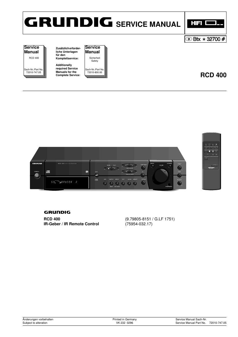
Grundig RCD 400 Service Manual

This is the 37 pages manual for Grundig RCD 400 Service Manual.
Read or download the pdf for free. If you want to contribute, please mail your pdfs to info@audioservicemanuals.com.

Page: 1 / 37
left right
Grundig RCD 400 Service Manual

Extracted text from Grundig RCD 400 Service Manual (Ocr-read)


Page 1

G R" n DIG SERVICE MANUAL HIFI III--

® th * 32700 #

Service Zusfilzlich erlorder- Service
Manual liche Unlerlagen Manual

liir den

HOD 400 Kompleitservice: Slchemeil
Salely

Additionally

5910th /Pan No. fiqulreld farm SachrNrJFan No.
72010774105 anua S or e 72010730000
Complete Service: RC D 400

GRU I'IDIG
RCD 400 (979805-8151 /G.LF 1751)
IR-Geber / IR Remote Control (75954-03217)
Anderungen vcrbehalien Printed m Germany Service Manual SachrNr.

Subject to alleraticn VK 232 0296 Service Manual Part No. 7201074705

Page 2

Allgemeiner Teil / General Section

H00 400

Es gelten die Vorschriften und Sicherheitshin-
weise gemaB dem Service Manual "Sicherheit",
Sach-Nummer 72010»800.00, sowie zusatzlich
die eventuell abweichenden, landesspezifischen
Vorschritten!

The regulations and safety instructions shall be
valid as provided by the "Safety" Service Manual,
part number 7201 O-800.00, as well as the
respective national deviations.

® Inhaltsverzeichnis

Seite
Allgemeiner Teil 1 - 2. 1 - 16
MeBgerate / MeBmittel . 1 - 2
Technische Daten . 1 - 3
Bedienhinweise . 1 - 4
Ausbauhinweise ................................................................... 1 - 13

Abgleichvorschriften 2 - 1...2 - 3

Platinenabbildungen

und Schaltplfine 3 - 1...3 - 21
Display ............

Netzteilplatte, Klangreglerplatte, Lautstarkeplatte
Druckplattenabbildungen:

CD (IC-BIock-Diagramme TDA1313T, SAA6579T).

Tuner ........ .......................................

Hauptplatte (IC-BIock-Diagramme TDA7294, LC7821) .

Kopfhorerplatte, Display- und Tastenplatten, Netzteilplatte,

Klangreglerplatte, Lautstarkeplatte ....................................... 3 - 19

Ersatzteilliste und

Explosionszeichnungen
Explosionszeichnung ROD 400 ......
Explosionszeichnung CD-Lautwerk
Ersatzteiliste ................................

Allgemeiner Teil

MeBgerfite / MeBmittel

Digitalvoltmeter, Wobbler, MeBsender, Stereokoder, Tongenerator,
Oszilloskop, NF-Voltmeter, KlirrtaktormeBgerat

Beachten Sie bitte das GRUNDIG Me Btechnik-Programm, das Sie unter
tolgender Adresse erhalten:

GRUNDIG electronics GmbH
Wflrzburger Str. 150
D-90766 Ftirth/Bay.

Tel. 0911/703-0

Teletax 091 11703-4479

Table of Contents

General Section
Test Equipment / Aids.
Specifications
Operating Hints .
Disassembly Instructions .............................................


..... 1 -13
Adjustment Procedures..................... 2 - 1...2 - 3

Layout of the PCBs

and Circuit Diagrams 3 - 1...3 - 21
Display ..........
Wiring Diagram .
Circuit Diagrams

Layout of PCBs:
CD (IC Block Diagrams TDA1313T, SAA6579T)
Tuner ..............................................................
Main Board (IC Block Diagrams TDA7294, LC7821) . 3 - 16
Headphone Board, Display and Key Boards, Mains
Volume Board ............................................................ 3 - 19


Spare Parts List and

Exploded Views.
Exploded View RCD 400
Exploded View CD Drive Mechanism
Spare Parts List ............................

4-1 .4

General Section

Test Equipment / Aids

Digital voltmeter, Sweep generator, Test generator, Stereo coder, AF
generator, Oscilloscope, AF voltmeter, Distortion meter

Please note the Grundig Catalog "Test and Measuring Equipment"
obtainable from:

GRUNDIG electronics GmbH
Wtlrzburger Str. 150
D-90766 Fflrth/Bay.

Tel. 0911/703-0

Teletax 0911/703-4479

GHUNDIG Service