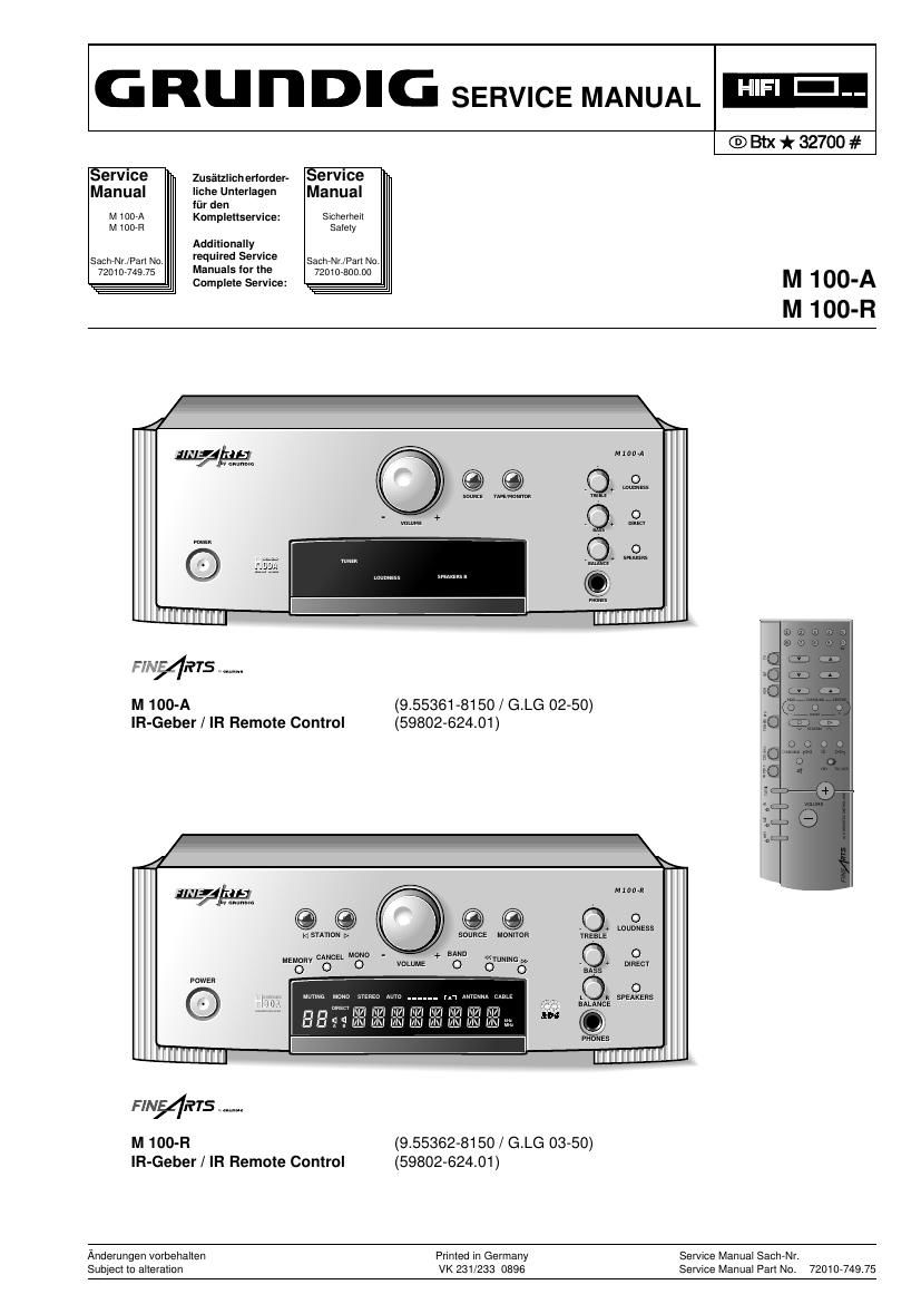
Grundig M 100 Service Manual

This is the 32 pages manual for Grundig M 100 Service Manual.
Read or download the pdf for free. If you want to contribute, please mail your pdfs to info@audioservicemanuals.com.

Page: 1 / 32
left right
Grundig M 100 Service Manual

Extracted text from Grundig M 100 Service Manual (Ocr-read)


Page 1

GRunDIG SERVICE MANUAL WEI

service Zusfilzlich erlorder- service
Manual Iiche Unierlagen Manual
liir den
M 1007A Komplellservice: Sicherheil
M 100R Salely
Additionally
SachrNrJPan No, required Sermce SachrNrJParl No.
7201074975 Manuals lor the 720104300 00

Complete Service:

®th*32700#

M 100-A
M 100-R

M74138

M 100-A
lR-Geber / IR Remote Control

sum nmunm

(9.55361 -81 50 / G.LG 02-50)
(59802-62401)

174%
@ ©

m s-rnnou [>1

MEMon
O

M 100-R
lR-Geber / IR Remote Control

CANDEL MON -
O

mums Mono stREo ma rn mam (mg L R SPEAKERS

L'u' WEN-141:1?"LI-14LU-1WIZI my
uuHmwmewmmm Oi

mom

0 0

SOURCE Mnmron mm:

-+ mu « O o
vow»: o OWN'NGév .ms mam

BALANCE

wanes

(955362-8150 / G.LG 03-50)
(59802-62401)

Anderungen vorbehalten
Subjecl lo alleration

Printed in Germany Service Manual SachrNr.
VK 231/233 0896 Service Manual Part No. 7201074975

Page 2

Allgemeiner Teil / General Section

M 1007A /M 100+?

Es gelten die Vorschritten und Sicherheitshin-
weise gemaB dem Service Manual "Sicherheit",
Sach-Nummer 72010-80000, sowie zusatzlich
die eventuell abweichenden, landesspezifischen
Vorschriften!

The regulations and safety instructions shall be
valid as provided by the "Safety" Service Manual,
part number 72010-80000, as well as the
respective national deviations.

®

lnhaltsverzeichnis


Allgemeiner Teil
MeBgerate / MeBmittel .
Technische Daten .....
Testmodus
Ausbauhinweis
Bedienhinweise ..

Abgleichvorschriften 2 - 1 2 - 3

Schaltplane und

Druckplattenabbildungen

Display ..

Schaltplane.
Netzteil
Tuner .
Eingangsplatte
Lautstarkereglerplatte, Klangreglerplatte, RC-Platte
NF-Ausgangsplatte, Kopfhorerbuchsenplatte . 3 - 15
Bedienteil M 100-R
Bedienteil M 100-A
Verstarkerplatte .....

Platinenabbildunge
Netztei

Eingangsp at e
Lautstarkereglerplatte, Klangreglerplatte, RC-Platte
NF-Ausgangsplatte, Kopfhorerbuchsenplatte .......
Bedienteil M 100-R
Bedienteil M 100-A
Verstarkerplatte ..
Verdrahtungsplan ..

Ersatzteillisten und

Explosionszeichnungen.
Explosionszeichnung M 100-A ......
Ersatzteilliste M 100-A
Explosionszeichnung M 100-R
Ersatzteilliste M 100-R

Allgemeiner Teil

MeBgerate / MeBmittel

Wobbler MeBsender
Stereocoder Tongenerator
Oszilloskop Digitalvoltmeter

NF-Voltmeter KlirrfaktorrneBgerat
Beachten Sie bitte das GRUNDIG MeBtechnik-Programm, das Sie
unter folgender Adresse erhalten:

GRUNDIG electronics GmbH
Wflrzburger Str. 150

D~90766 Fflrth/Bay

Tel. 0911/703-0, Fax 0911/703-4479

Table of Contents


General Section.
Test Equipment / Aids
Technical Data ........
Test Mode ..................
Disassembly Instructions
Operating Hints ...........

Adjustment Procedures 2 - 22 - 3

Circuit Diagrams and

Layout of PCBs .
Display .................
Circuit Diagrams.
Mains Unit
Tuner
Input Board
Volume Control Board, Tone Control Board, RC-Board
AF Output Board, Headphone Socket Board
Control Board M 100-R
Control Board M 100-A
Amplifier Board ...................................................................... 3 - 22
Layout of PCBs:
Mains Uni


Volume Control Board, Tone Control Board, RC-Board
AF Output Board, Headphone Socket Board .............
Control Board M 100-R
Control Board M 100-A
Amplifier Board .
Wiring Diagram


Spare Parts Lists and

Exploded Views.
Exploded View M 100-A
Spare Parts List M 100-A
Exploded View M 100-R
Spare Parts List M 100-R

General Section

Test Equipment / Aids

Sweep generator
Stereo coder
Oscilloscope
AF-Voltmeter

Test generator
AF-generator
Digital voltmeter
Distortion meter

Please note the Grundig Catalog Test and Measuring Equipment"
obtainable from:

GRUNDIG electronics GmbH
Wflrzburger Str. 150

D-90766 Fflrth/Bay

Tel. 0911/703-0, Fax 0911/703-4479

GHUNDIG Service