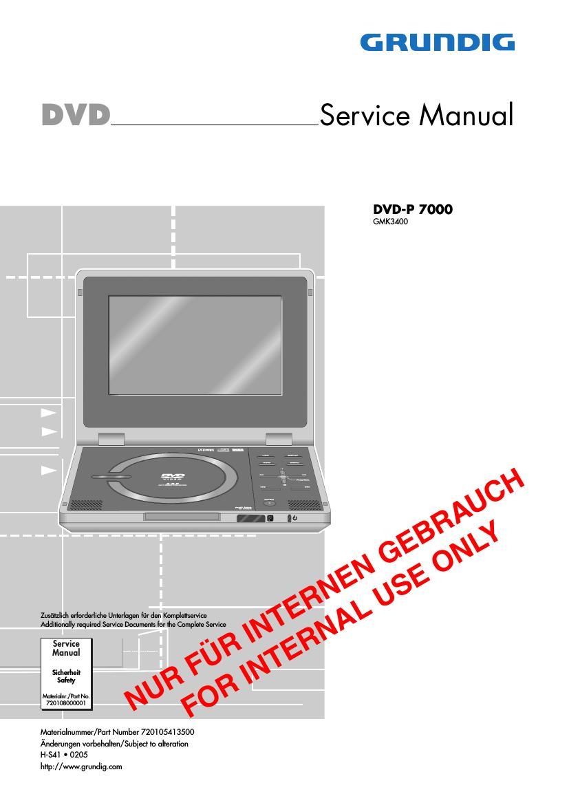
Grundig DVDP 7000 Service Manual

This is the 42 pages manual for Grundig DVDP 7000 Service Manual.
Read or download the pdf for free. If you want to contribute, please mail your pdfs to info@audioservicemanuals.com.

Page: 1 / 42
left right
Grundig DVDP 7000 Service Manual

Extracted text from Grundig DVDP 7000 Service Manual (Ocr-read)


Page 2

GRUNDIG Service

DVDVP 7000

Es gelten die Vorschriften und Sicherheitshinweise
gemaB dem Service Manual "Sicherheit", Material-
nummer 720108000001, sowie zusatzlich die eventu-
ell abweichenden, landesspezifischen Vorschriften!

The regulations and safety instructions shall be valid
as provided by the "Safety" Service Manual, part
number 720108000001, as well as the respective
national deviations.

lnhaltsverzeichnis
Seite

Allgemeiner Teil .. .1-2...1-16

Allgemeine Hinweise 1-2
Technische Daten 1-3
Software-Upgrade 1-3
Servicehinweise 1-4
Bedienhinweise 1-6

Platinenabbildungen und

Schaltplane
Netzteilplatte .
Hauptplatte
- Prozessor
- Speicher.
- Audio
- AV-Anschlusse.
DVD-Frontend
- Motorsteuerung
- lR-Empfanger / LED-Steuerung
- Display-Verbindungen
Keyboard.
Tuner (Option)
Displayplatte .
- Netzteil .........
- Video-Prozesso
- Display-Treiber.
Oszillogramme
lC-Blockschaltplane

. 2-1 ...2-20


Explosionszeichnungen
und Ersatzteilliste 3-1...3-6

Allgemeiner Teil

Allgemeine Hinweise
Vor dem Offnen des Gehauses den Netzstecker ziehen!
Achtung: ESD-Vorschriften beachten (A.

Leitungsverlegung

Bevor Sie die Leitungen und insbesondere die Masseleitungen Ibsen,
muss die Leitungsverlegung zu den einzelnen Baugruppen beachtet
werden.

Nach erfolgter Reparatur ist es notwendig, die Leitungsfiihrung wieder
in den werkseitigen Zustand zu versetzen um evtl. spatere Ausfalle
oder Stb'rungen zu vermeiden.

Durchfiihren von Messungen

Bei Messungen mit dem Oszilloskop an Halbleitern sollten Sie nur
Tastképfe mit 10:1 - Teiler verwenden. AuBerdem ist zu beachten,
dass nach vorheriger Messung mit AC-Kopplung der Koppelkonden-
sator des Oszilloskops aufgeladen sein kann. Durch die Entladung
fiber das Messobjekt kbnnen Bauteile beschadigt werden.

Messwerte und Oszillogramme
Bei den in den Schaltplanen und Oszillogrammen angegebenen
Messwerten handelt es sich um Naherungswerte!

Table of Contents

Page
1-2...1-16
1-2
1-3
1-3

General Section ..
General Notes.
Technical Data
Software Upgrade

Sen/ice Hints 1-4
Operating Hints .. . 1-11
Layout of PCBs and

Circuit Diagrams .. 2-1...2-20
Power Supply Board . 2-1
Main Board ............ 2-4
- Processor. 2-6
- Memory 2-7

- Audio.
- AV Connections
DVD Frontend
- Motor Control .
- lFt Receiver/LED Contro
- Display Connections
Keyboard
Tuner (Option).
Display Board ..
- Power Supply .
- Video Processor
- Display Driver.
Oscillograms ......
lC Block Diagrams

2-8
2-9
. 2-10
. 2-11
. 2-12
. 2-13
. 2-14
. 2-14
. 2-15
. 2-15
. 2-16
. 2-17
. 2-18
. 2-20

Exploded Views
and Spare Parts List 3-1...3-6

General Section

General Notes

Before opening the cabinet disconnect the mains plug!
Attention: Observe the ESD safety regulations [4

Wiring

Before disconnecting any leads and especially the earth connecting
leads obsen/e the way they are routed to the individual assemblies.
On completion of the repairs the leads must be laid out as originally
fitted at the factory to avoid later failures or disturbances.

Carrying out Measurements

When making measurements on semi-conductors with an oscillo-
scope, ensure that the test probe is set to 10:1 dividing factor. If the
previous measurement was made on AC input, please note that the
coupling capacitor in the oscilloscope will be charged. Discharge via
the item being checked can damage the components.

Measured Values and Oscillograms
The measured values given in the circuit diagrams and oscillograms
are approximates!