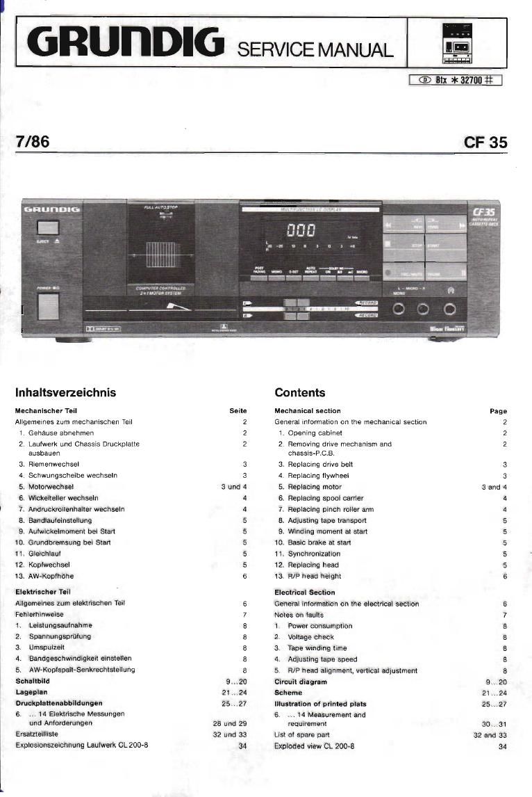
Grundig CF 35 Service Manual

This is the 16 pages manual for Grundig CF 35 Service Manual.
Read or download the pdf for free. If you want to contribute, please mail your pdfs to info@audioservicemanuals.com.

Page: 1 / 16
left right
Grundig CF 35 Service Manual

Extracted text from Grundig CF 35 Service Manual (Ocr-read)


Page 1

GRUTIDIG

SERVICE MANUAL

n
lei

7/86

th * 32701]

CF35

GRUIIDIO

Inhaltsverzeichnis

Mechanlschcr Teil
Allgemeines zum mechanischen Tell
1. Gehause abnehmen

2. Lautwem und Chassis Druckplatte
ausbauen

. Riemenwechsel
. Schwungscheibe wechselri

3

4

5. Moiorwechsel

6 Wickelteller wechseln
7. Andruckmllenhalter wechseln
8. Bandlauieinslellung

9. Aufwickelmoment bei Start
10. Gmndbremsung bei Start
11 Gleichlaul

12. Konlwechsel

13. AWeKoplhdhe

Elektrischer Teil

Allgemeines zum elektrischen Tail

Fehlerhinweise
Leislungsaulnahme

2. Spannungsprulung

3. Umspulzeit

4. Bandgeschwindigkeil einstellen
5, AW-Koplspalt-Senkrechtstellung
Sohaltbild

Lageplan
Druckulattenabbildungan

6. 14 Eleklrisctie Messungen

und Anforderungen
Ersalneilliste

Explosionszeichnung Laufwerk CL 200-8

Seite

Sund4

mmwumma

mmwmmflm

9...20
21...24
25...27

28 und 29
32 und 33
34

Contents

Mechanical section
General inlormation on the mechanical section

1
2

mxicnaihc.)

11

12,

13

. Opening cablnet

Removing drive mechanism and
chassis-ROB.

. Replacing drive belt

Replacing llywheel

, Replacing motor
. Replacing spool carrier

Replacing pinch roller arm

. Adjusting tape transport
9.
10.

Winding moment at stan
Basic brake at start
Synchronization
Replacing head

R/F head height

Electrical Section

General information on the electrical section
Notes on taults

mewwe

Power consumption

Voltage check

Tape winding lime

Adjusting tape speed

R/P head alignment, vertical adjustment

Circuit diagram
Scheme

Illustration o! printed plots

6.

14 Measurement and
requirement

List 01 spare part
Exploded view Ct. 200-8

Page

3and4

mwmmwmt.

gamma-mum

9.20
21..,24
25 . 27

30.. 31
32 and 33
34

Page 2

Mechanischer Teil: CF 35

Allgemeines zum mechanischen Tell

Bei mechanisoh en Arbeiten lst daraut ZU ecnten, deli der Netzslecker ge-
zogen ist.

Die Zahien im Text und bei den Abbildungen sind mit den Posrtionsnum-
mern In der Ersatzteilliste CF35 ubereinstimmend. lst den Positionsnum-
mern ein LW vorgesetzt, sind die Teile in der Ersatzteilliste CL 200-8 aufge-
it'll'lrt.

Teile die nichl in den Ersatzteillisten vorkommen. Sind mit Buchstaben ge-
kennzeichnet.

Sperrscheiben sollten bei einem Wechselvon Bauteilen erneuerl werden.
da sonst der Sicherungsetlekt nichl gewahrleistet let.

1. Gehéuse abnehmen (Abb. 1)
- 4 Schrauben a herausdrehen.
- Gehause b nach oben wegnehmen,

Abb. 1 Fig. 1

2. Laufwerk CL 2004 und Chassis Druckplatte ausbauan (ADD. 2 u. 3)

Sara! iIn FunKtion Stop bringen. der Koplschiitten ist dabei 'zuruckge-
lahren (Netzstecker zrehen).

Gehause Pkt. 1 abnehmen,

Schubstange 21 aushahgen.

Steckverbindung 15A zur Dispiayplatte abziehen.
- 4 Schrauben C herausdrehen (Abt) 2)

7 1 Schraube d (Belesligungsschraubelieren Stfltzwlnkel,Abb. 3) here
ausdrehen.

2 Schrauberi aus derBlechhalterung turdieLlNE IN. LlNEOUTund der
DIN-Buohse herausdrehen.

Frontbleride i, Chassis-Druckpiatte A und Lautwerk CL 200-8 nech
vome schieben und aus den Bodenlaschen heben.

3 Schrauben d herausdrehen,
- Laufwerk nach hinten wegnehmeri
Der Einbau erlolgt in umgekehrter Reihentolge.

a. Stackverbindungen zum Laufwerk CL 200-8 abzietien.

16 A Bandkennung

8 A AufnahmeWiedergabekopt
15 A Servoplatte
14 A Optokoopierplatte
17 A WiCkeI: Servo- und Tonwellerimotor

9 A Loschkopl

und evenluell 18A Displayplatte

Mechanical Section CF 35

General information on the mechanical section

Ensure that the mains supply Is disconnected belore beginning mechani-
cal work on the recorder.

Numbers used in the text and in the illustrations are the same as those
used in the CF 35 spare parts list. The oretix LW indicates thatthe part With
this item number is to be found In the CL 200-8 spare parts list

A letter indicates a part not Included in the spare parts lists

Always tit new locking washers on reassembly, as the security otare-used
washer connot be guaranteed.

1. Opening cablnet (Fig. 1]
- Remove 4 screws a.
- Lift oti cabinet b.

2. Removing drive mechanism CL 200-8 and Chassis-RC3.
(Fig, 2 and 3)

- Retrect head carrier by selecting STOP function. Disconnect mains
supply.

Open cabinet as in 1 above,

Disconnect thrust bar 21

7 Remove contact 18A to the display board.

- Remove 4 screws 0 (Fig. 2)

Remove t screw (1 (angie support. Hg. 3)

Remove 2 screws from the metal support for LINE IN. LlNE OUT and the
DIN-socket.

- Slide Iront screen 1, chassis printed plate A and drive mechanism
CL 200-8 to the lront and Hit same out at the button flaps.

Remove 3 screws d.
- Withdraw drive mechanism toward rear.
Reassembly is reverse of above sequence,

Remove connections to drive mechanism CL 200-8
16 A Tape recognition

5 A Record-playback head

15 A Servo board
14 A Ontocoupler board
17 A Winding-senro- and capstan motor

9 A Erase head

possible 18 A displayboard

Boden

B O
Abb. 2 ° m Fig. 2