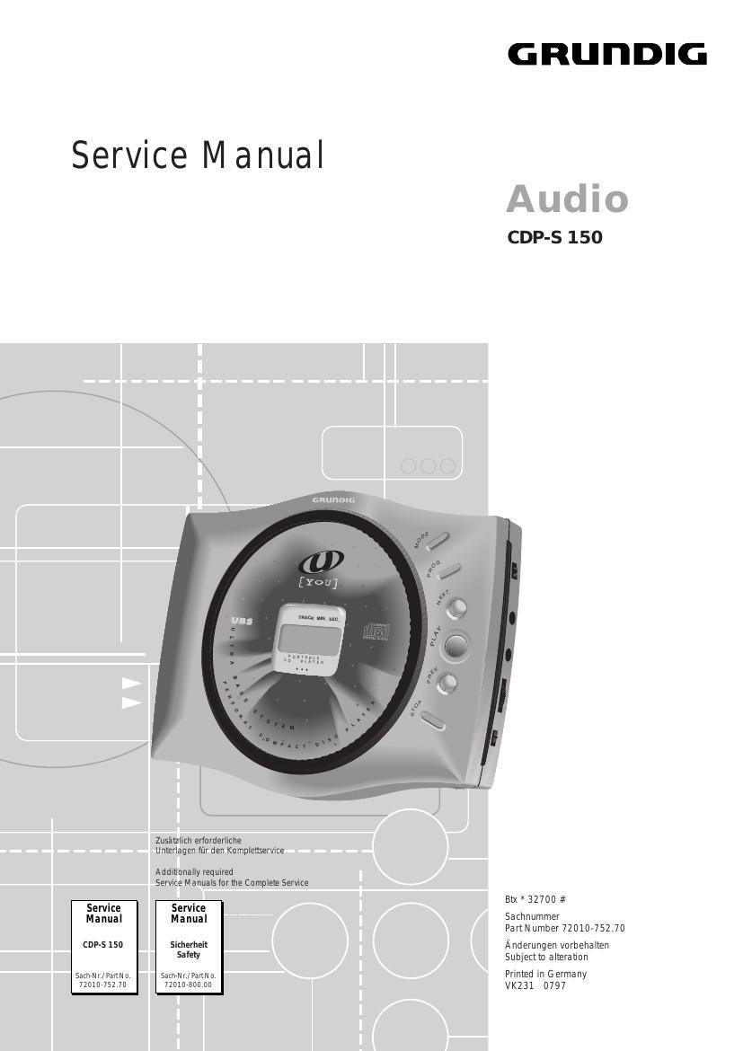
Grundig CDPS 150 Service Manual

This is the 12 pages manual for Grundig CDPS 150 Service Manual.
Read or download the pdf for free. If you want to contribute, please mail your pdfs to info@audioservicemanuals.com.

Page: 1 / 12
left right
Grundig CDPS 150 Service Manual

Extracted text from Grundig CDPS 150 Service Manual (Ocr-read)


Page 1

1 - 2GRUNDIG Service Allgemeiner Teil / General SectionCDP-S 150 Es gelten die Vorschriften und Sicherheitshin- weise gemŠ§ dem Service Manual "Sicherheit", Sach-Nummer 72010-800.00, sowie zusŠtzlich die eventuell abweichenden, landesspezifischen Vorschriften!The regulations and safety instructions shall be valid as provided by the "Safety" Service Manual, part number 72010-800.00, as well as the respective national deviations. k Table of Contents Page General Section ............................. 1 - 2 É 1 - 7 Test Equipment / Aids ............................................................... 1 - 2 Technical Data .......................................................................... 1 - 3 Service Hints ............................................................................. 1 - 3 Operating Instructions ............................................................... 1 - 5 Disassembly Instructions .......................................................... 1 - 6 Circuit Diagrams and Layout of the PCB .................. 2 - 1 É 2 - 5 Layout of the PCB ..................................................................... 2 - 1 Circuit Diagram ......................................................................... 2 - 2 IC Block Diagrams .................................................................... 2 - 4 Exploded Views and Spare Parts List ............................. 3 - 1 É 3 - 2 Exploded Views ........................................................................ 3 - 1 Spare Parts List ........................................................................ 3 - 2 j Inhaltsverzeichnis Seite Allgemeiner Teil ............................ 1 - 2 É 1 - 7 Me§gerŠte / Me§mittel .............................................................. 1 - 2 Technische Daten ..................................................................... 1 - 3 Servicehinweise ........................................................................ 1 - 3 Bedienhinweise ......................................................................... 1 - 4 Ausbauhinweise ........................................................................ 1 - 6 SchaltplŠne und Druckplattenabbildung ................. 2 - 1 É 2 - 5 Druckplattenabbildung .............................................................. 2 - 1 Schaltplan ................................................................................. 2 - 2 IC-Blockdiagramme .................................................................. 2 - 4 Explosionszeichnungen und Ersatzteilliste ......................... 3 - 1 É 3 - 2 Explosionszeichnungen ............................................................ 3 - 1 Ersatzteilliste ............................................................................. 3 - 2 Allgemeiner Teil Me§gerŠte / Me§mittel Beachten Sie bitte das GRUNDIG Me§technik-Programm, das Sie unter folgender Adresse erhalten: GRUNDIG Instruments Test- und Me§systeme GmbH WŸrzburger Str. 150 D-90766 FŸrth/Bay Tel. 0911/703-4118, Fax 0911/703-4130 General Section Test Equipment / Aids Please note the Grundig Catalog "Test and Measuring Equipment" obtainable from: GRUNDIG Instruments Test- und Me§systeme GmbH WŸrzburger Str. 150 D-90766 FŸrth/Bay Tel. 0911/703-4118, Fax 0911/703-4130

Page 2

CDP-S 150Allgemeiner Teil / General Section GRUNDIG Service1 - 3 Technische Daten Spannungsversorgung AC Netzadapter .......................................................... DC 3V extern Batteriebetrieb .......................................... 2 x 1,5V (LR6, UM3, AA) Ausgangsleistung (DIN 45324, 10% THD) Ohrhšrer ........................................................................... 2 x 15mW Line Out ........................................................................ 0,6V ± 1,5dB AnschlŸsse Line Out .................................................................. 3,5mm ¿, stereo DC Buchse .............................................................. 3,5mm ¿, (3,0V) Ohrhšrer .................................................................. 3,5mm ¿, stereo CD-Teil FrequenzŸbertragungsbereich ..................................... 20Hz - 20kHz GerŠuschspannungsabstand ................................................. > 80dB Kanaltrennung ........................................................................ > 52dB D/A-Umsetzung ........................................ 1 bit linear 4 fs digital filter Technical Data Power Supply AC power adapter ...................................................... DC 3V extern Battery operation ...................................... 2 x 1.5V (LR6, UM3, AA) Output power (DIN 45324, 10% THD) Earphone output ............................................................... 2 x 15mW Line output .................................................................... 0.6V ± 1.5dB Connections Line Out .................................................................. 3.5mm ¿, stereo DC connector .......................................................... 3.5mm ¿, (3.0V) Earphones ............................................................... 3.5mm ¿, stereo CD Player Frequency range .......................................................... 20Hz - 20kHz S/N ratio, weighted ................................................................. > 80dB Channel separation ................................................................ > 52dB D/A conversion ......................................... 1 bit linear 4 fs digital filter Service Hints Accumulators The mains adapter NR 30-6 also works as a charger for Ni-Cd accumulators with the reference AA IEC (KR 15/51) 1.2V/600mA. Make sure that the metal cap on the negative pole is stripped more than 3mm (as illustrated). Otherwise the accumulator will not be charged! Laser Unit When removing the drive mechanism, the flexprint must be provided with a protective soldered joint before unplugging the flexprint con- nector to avoid damage to the laser diode by static charges. When inserting the new drive mechanism the soldered joint fitted at the factory must be removed after the flexprint is plugged in. Flexprint Servicehinweise Akkus Der Netzadapter NR 30-6 dient auch als LadegerŠt fŸr Nickel- Cadmium-Akkus mit der Bezeichnung AA IEC (KR 15/51) 1,2V/ 600mA. Achten Sie darauf, da§ das Metallende am Minuspol mindestens 3mm abisoliert ist (wie abgebildet). Ist dies nicht der Fall, wird der Akku nicht geladen! Lasereinheit Beim Ausbau des Laufwerkes mu§ vor Abziehen der Flexprint- Steckverbindung eine Schutzlštstelle auf der Flexprintleitung der Lasereinheit angebracht werden, um eine Zerstšrung der Laser- diode durch statische Aufladung zu vermeiden. Beim Einbau eines neuen Laufwerkes mu§ nach Einstecken der Flexprintleitung die werkseitig angebrachte Schutzlštstelle ent- fernt werden! Schutzlštstelle protective soldered joint 3 mm min3mmmin abisoliert stripped