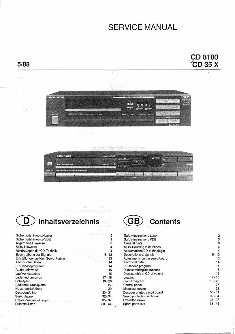
Grundig CD 35X 8100 Schematics
This is the 12 pages manual for Grundig CD 35X 8100 Schematics.
Read or download the pdf for free. If you want to contribute, please upload pdfs to audioservicemanuals.wetransfer.com.
Page: 1 / 12