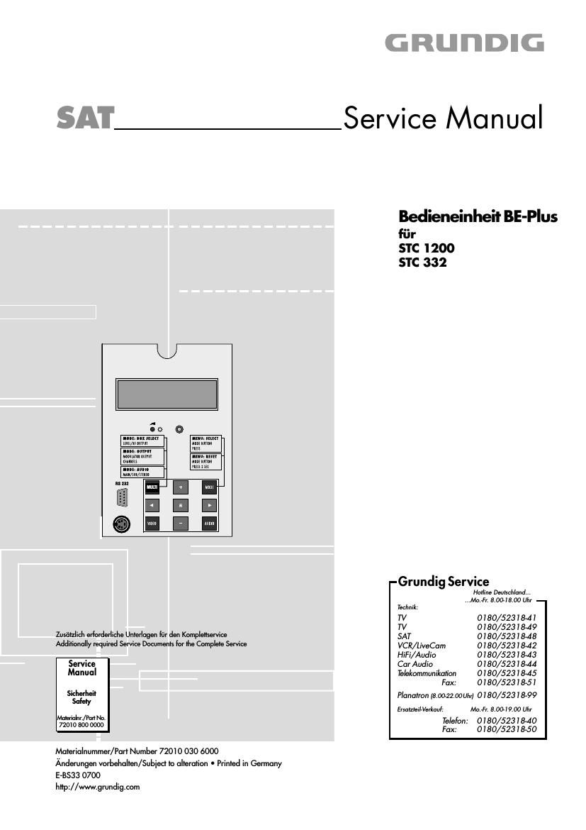
Grundig BE plus Service Manual

This is the 6 pages manual for Grundig BE plus Service Manual.
Read or download the pdf for free. If you want to contribute, please mail your pdfs to info@audioservicemanuals.com.

Page: 1 / 6
left right
Grundig BE plus Service Manual

Extracted text from Grundig BE plus Service Manual (Ocr-read)


Page 2

Allgemeiner Teil / General Section

STC 1200 /332

Es gelten die Vorschriften und Sicherheitshin»
weise gemaB dem Service Manual "Sicherheit",
Materialnummer 72010 800 0000, sowie zusatz-
lich die eventuell abweichenden, landes-
spezifischen Vorschriften!

The regulations and safety instructions shall be
valid as provided bythe "Safety" Service Manual,
part number 72010 800 0000, as well as the
respective national deviations.

Die Bedieneinheit BE-Plus wird in die Kopfstationen STC1200 und
STC332 eingebaut und ist riickwarts kompatibel zu der bisher einge-
bauten Bedieneinheit.

Der Unterschied bei der Bedieneinheit ist die FIash-Programmierung.

Grundlage fiir den Service sind:

- Service Manual STC1200 (Materialnummer 72010 023 3000)
- Service Manual STC332 (Materialnummer 72010 023 7000)

- Service Manual "Sicherheit" (Materialnummer 72010 800 0000)

lnhaltsverzeichnis

Seite
Allgemeiner Teil 2

Softwarestand abfragen .. 2
Software-Programmierung 2
[086010 (Speicher) .. 2
Platinenabbildungen.................................. 3...6
und Schaltplane

Bedieneinheit 3

Ersatzteilliste 7

Allgemeiner Teil

Sofiwarestand abfragen

- FUr ca. 3sec. zwei beliebige Tasten (LB. "Mode" und "Multi")
gleichzeitig driicken.

Im Display wird der Softwarestand angezeigt.

Software: 7 7 7 7

Software-Programmierung

- Benotigt wird ein Computer mit Win 95 / 98 / 2000 / NT

- Gerate-Software

- Update-Software

- Kabel mit 9-poligem Sub-D-Stecker auf 9-polige Sub-D-Buchse
(handelsiiblich)

STC 1200 / 3:2
epoi. SuerrSIecker
97pm Suer piug

- Die 9-polige Sub-D-Buchse der STC 1200 / 332 fiber handelsiibli-
ches Kabel mit dem 9-poligen Sub-D-Stecker des PC verbinden.

- Stecker des Netzkabels der Kopfstation in Netzsteckdose stecken.

- Update-Software starten.

Bedienung siehe On-Line-Hilfe.

Hinweis:

Mit der Update Software ko'nnen unter Punkt "Einstelldaten lesen" die

Daten aus der Kopfstation ausgelesen werden.

|C86010 (Speicher)

[m |086010 werden alle individuellen Einstellungen gespeichert.
Beim Tausch der Bedieneinheit kann der gesockelte IC in die neue
Bedieneinheit eingesetzt werden.

Es sind somit die alten Einstellungen erhalten.

lllll

The control unit BE-Plus is fitted into the head stations STC 1200 and
STC 332 and is downward compatibel to the control units incorporated
till today.

The difference between the control units is the Flash programming.

Basic instructions for servicing are given in the:

- Service Manual STC1200 (Part number 72010 023 3000)
- Service Manual STC332 (Part number 72010 023 7000)
- Service Manual "Safety" (Part number 72010 800 0000)

Table of Contents

Page
General Section 2
Calling up the software version
Software programming
|086010 (memory) .....

NNN

Layout of the P.C.B. 3...6
and Circuit Diagrams
Control Unit 3

Spare Parts List 7

General Section

Calling up the software version

- Press any two keys for about 3 seconds (e.g. "Mode" and "Multi") at
the same time.

The software version is shown in the display.

Software: 7 7 7 7

Software programming

- You need: a computer with Win 95 / 98 l2000 / NT

- the device software

- the update software

- a cable with 9-pin Sub-D plug to 9-pin Sub-D socket
(commercial standard)

PC
Spot. SuerrBuchse
97m" 811er socket

- Connect the 9-pin Sub-D socket on the STC 1200 / 332 via a
commercial cable with the 9-pin Sub-D plug on the PC.

- Connect the mains cable plug of the head station with awall outlet.

- Run the update software.

See the online help for the steps to follow.

Hint:

It is possible to read out the data via the function "Einstelldaten lesen

of the update software.

IC86010 (memory)

All individual settings are stored in the |C86010.

When replacing the control unit itis possibleto insertthe |C intothe new
control unit. All settings then are maintained.

2

GRUNDIG Service