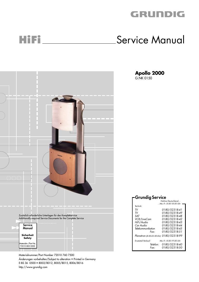
Grundig APOLLO 2000 Service Manual

This is the 16 pages manual for Grundig APOLLO 2000 Service Manual.
Read or download the pdf for free. If you want to contribute, please mail your pdfs to info@audioservicemanuals.com.

Page: 1 / 16
left right
Grundig APOLLO 2000 Service Manual

Extracted text from Grundig APOLLO 2000 Service Manual (Ocr-read)


Page 2

Allgemeiner Teil / General Section

Apollo 2000

Es gelten die Vorschriften und Sicherheitshinweise
gemaB dem Service Manual "Sicherheit", Material-
nummer 72010 800 0000, sowie zusatzlich die even-
tuell abweichenden, landesspezifischen Vorschriften!

The regulations and safety instructions shall be valid
as provided by the "Safety" Service Manual, part
number 72010 800 0000, as well as the respective
national deviations.

lnhaltsverzeichnis
Seite
Allgemeiner Teil 1 - 2 1 -

Servicehinweis
Technische Daten.
Ausbauhtnweise.
Bedienhinweise ..


Schaltplane und

Druckplattenabblldungen 2 -1 2 - 10
Verdrahtungsplan ............................................................................. 2 - 1
Schaltplane
NF-Verstarker-Platte
Control-Platte ........
Netzteil .................................................................................... 2 - 10
Druckplattenabbitdungen
NF»Verstarker-Platte
Control-Platte ........
Netzansch|u6»Platte.
Netzschalter-Platte .....................................................................

Explosionszeichnung

und Ersatzteilliste. 3 -1 3 - 2

Allgemeiner Teil

Messgerate / Messmittel

Beachten Ste bitte das GRUNDIG Messtechnik»Programm, das Sie unter
folgender Adresse erhalten:

Table of Contents


Page
General Section............................. 1 - 21 -
Service Hint... 1 - 2
Technical Data 1 - 2
Disassembly Instructions 1 - 3
Operating Hints 1- 7

Circuit Diagrams and

Layout of PCBs 2 -1 2 - 10

Wiring Diagram ................................................................................ 2 -1
Circuit Diagrams
Power Amplifier Board
Control Board ..........
Power Supply ............................................................................. 2 - 10
Layout of PCBs
Power Amplifier Board
Control Board
Mains Con Board
Mains Switch Board ...................................................................


Exploded View and
Spare Parts List..

General Section

Test Equipment / Aids

Please note the Grundig Catalog "Test and Measuring Equipment" obtain-
able from:

GRUNDIG Instruments Test- und Messsysteme GmbH
Wfirzburger Str. 150, D 90766 FflrthlBay
Tel. 0911/7034118, Fax 0911/703-4130
eMail: instruments@grundig.de; Internet: http:l/www.grundig-insfruments.de

Servicehinweis

Die Daten- und Analog-Funkmodule dflrfen nur durch autorisierte
Fachbetriebe repariert werden und miissen daher im Defektfall kom-
plefl gefauscht werden.

Technische Daten

Sinusleistung 200W
Musiklelstung 360W
Eingangsempflndlichkelt/ Impedanz . 500mV/47kfl


Signal-RauschaAbstand >95dB
Klirrfaktor (-1db, SQ, 1kHz) . 0,01%
Netz .................... 230V / 50/60HZ

360W
<2W

Leistungsaufnahme
Standby Leistungsaufnahme

1 x cinch

863 885MHz
868 870MHz

..... 4
30Hz 25kHz
200HZ / 5.000HZ

Eingang fflr Vorverstarker

Frequenz der NF-Ubertragung
Frequenz der Datenfibertragung

Eautsprecher .........
gbenragungsbereich
Ubernahme-Frequenze

Service Hint

The Data and Analog RF Modules are allowed to be repaired only by
authorized dealers and are to be exchanged completely in case of any
defect.

Technical Data

Nominal power
Music power ..
Input sensitivtty / Impedance .
Signal-to-noise ratio .......
Distortion (-1db, 89, 1kHz)

Mains
Power consumption
Standby power consumption .

200W

.. 360W
500mV / 47k!)
. >95dB
. 0.01%

230V / 50/60HZ
360W
<2W


1 x cinch

863 865MHz
868 870MHz

4
30Hz 25kHz
200HZ / 5.000HZ

Pre-amp in .........................

Frequency for audio transmission
Frequency for data transmission


Number of speakers
Transmission range
Crossover frequency

GHUNDIG Service