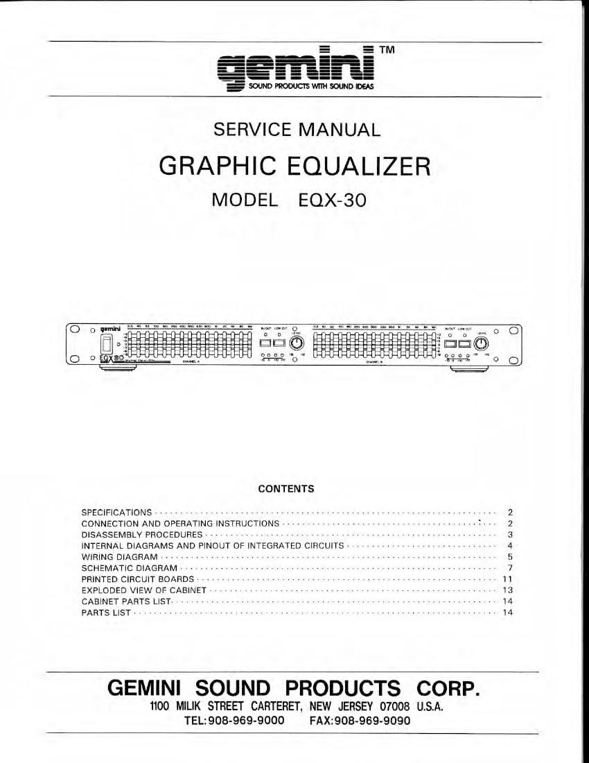
Gemini sound eqx 30 service manual

This is the 15 pages manual for gemini sound eqx 30 service manual.
Read or download the pdf for free. If you want to contribute, please mail your pdfs to info@audioservicemanuals.com.

Page: 1 / 15
left right
gemini sound eqx 30 service manual

Extracted text from gemini sound eqx 30 service manual (Ocr-read)


Page 1

.4
E

_-_-_-
__---
----------_
- - - -
u- - - - --
- - --
-_ - - _- -

-_SQJNDWJCISWITHWDM

SERVICE MANUAL

GRAPHIC EQUALIZER
MODEL EQX-BO

CONTENTS

SPECIFICATIONS , ...... . . .. .., .
CONNECTION AND OPERATING INSTRUCTIONS » . ..... T.

DISASSEMBLY PROCEDURES >

INTERNAL DIAGRAMS AND PINOUT OF INTEGRATED CIRCUITS

WIRING DIAGRAM ------ , »»»»»
SCHEMATIC DIAGRAM ------------

PRINTED CIRCUIT BOARDS - ---~ v v

EXPLODED VIEW OF CABINET - ..,

CABINET PARTS LIST v I - - - v vvvvvvvv

PARTS LIST ......................

GEMINI SOUND PRODUCTS CORP.

1100 MILIK STREET CARTERET. NEW JERSEY 07008 U.S.A.
TEL:908-969-9000 FAX:908-969-9090

Page 2

SPECIFICATIONS

EOX»30
Channels: 2 Channels
Bands: 15 Bands/Channel

31.5,40,63,100,160
250,400,500,630,800
1K,2K,4K,8K,16KH2

Input Impedance: 1.2K ohm
Output Impedance: 20K ohm
Maximum Output Level: 5.5 volts

Level Control: +/- 12 dB

CONNECTION AND OPERATING INSTRUCTION

S/ N Ratio:
Distortion:
Other Features:

Power:

Power Consumption:
Dimensions:

Weight:

90 dB

0.03%

ln/Out Pass Switch

Low Cut Switch

Level Display -10 --+17dB
120/230 volts

15 watts
19"(W)X2"IH)X101/2"(Dl
8 1/4 LBS.

INSTRUCTIONS FOR CONNECTION

1. Be sure that POWER (1) is in the OFF position. All

connections must be made with all equipment OFF.

Before plugging in the POWER CORD (8) make
sure the VOLTAGE SELECTOR SWITCH (9) is set
to the correct voltage. (The unit is preset to 110V).
Insert the power cord into a proper source.

. For best sound use only high quality audio cables
when hooking up this equalizer. Make sure that
all cable are pushed in securely.

. Make sure you correctly attach the patch cable for
the input source and output signal.

OPERATING INSTRUCTIONS

1. POWER 0N I1)

Once you have made all source connections to
your equalizer. Press the POWER (1) button The
POWER LED (2) will light up indicating that the

equalizer is on. Press again to turn the power off.

2. IN/OUT PASSING SWITCH (3i

3.

4.

Press this switch in. The equalizer will be activated.
Press it again to out. The signal will passed.

GRAPHIC EOUALIZER (4)
These sliders allow adiustment upto : 12dB each
octaves from 3.15 Hz (20 Hz) to 16 KHz I20 KHZ)

LEVEL ADJUSTMENT CONTROL (5)

You can obtain a proper output signal level using
this level control. The LEVEL DISPLAY LEDS (6)
will indicate you the exact output level from 10
dB to +17 dB in 4-steps. When the +17 dB led
light up. It tells you that there is too much output
power calibrated to produced distortion, lower the
level control gradually until this led goes off.

. LOW CUT SWITCH I7)

The low-cut switch attenuattes the muddy and
unwanted sound created by your source equipment
especially form the record player.

8
:5 W' is: aginiiuatt 3
I i fig
is 13

9 l