Gallien krueger 1000 rb volume 2 service manual

This is the 24 pages manual for gallien krueger 1000 rb volume 2 service manual.
Read or download the pdf for free. If you want to contribute, please mail your pdfs to info@audioservicemanuals.com.

Page: 1 / 24
left right
gallien krueger 1000 rb volume 2 service manual

Extracted text from gallien krueger 1000 rb volume 2 service manual (Ocr-read)


Page 2

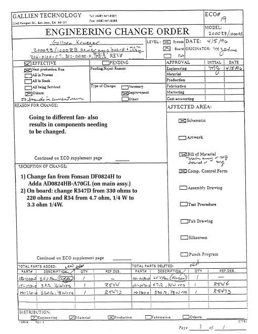
ENGINEERING CHANGE ORDER

ECO§

23

GALLIEN TECHNOLOGY
2240 iurugnn Dr..

San Jose. CA 95131

Tel: lJilhl 441-30
Fax: (408i «Hi-SUSS

MODEL:
1000 ZOOORB

D Continued on ECO Supplement Page

El

Dran'ingls) attached

CUSTOMER: SALUEN. KRTZECER_______ . _____- _ m cl: S}.<1cm DATE: «won
DESC: ngmomnmmnwm__.____-__ ,. - , 1:] Board omctxnon:
ASS\'#'S: Afll-(lOOO-O _Old Rev. __ D Fab .\1 lohns
SIEME-Juifllzlfifliflflfll--- .. __ -\ R¢~ _____ .__-, Chetkcd in:
' EFFECTIVE D PENDING B RELATED ECOS FOR:
New production Run Pending/'rejcct reason: E R2 Board:
All in Process D Loaded Board:
[3] A11 In Stock [3 Sheet Metal:
i2] All being serviced D Necessary change D Hatsink:
m l at i 83v fl 7,, pou e1: amp Improvement D
D boards are being used a To nreVent failure D
REASON FOR CHANGE: AFFECTED AREA: Bx: Date:
Heat sink does not have enough support causing transistor D Schematic
leads to break. D Board Artuork
D Board BOM
This ECO 15 to be done instead of the pre\ious ECO (#221 D Reference Des.
There ts no drilling required ith this one. E Main Asy BOM
Comp cntrl frm.
Assembly DWg.
- U Test Procedure
D Fab DraWing
D Silkscreen
D Continued on ECO Supplement Page D Punch Program
DESCRIPTION OF CHANGE: D Auto Insert Pgm
1) If unit isnt already assembled. disassemble it tn the point of MRBQ) 1 Change
removing the pewer amp board or boards from the unit.
2) Remove the bolts from Q589 and QSGS (looking at bottom of
the board. these are the bottom-left and tnp~left power trans.1 DISTRIB'LTIOX:
3') Place the bracket so that the two holes with tape line up over Engineering
the holes Where the bolts were removed (you may haVe to poke D Purchasing
through the tape) ( l3l ° 5 8 8 0) Main Assembly
4) Replace the bolts where they were removed from. without D P.C. Assy
the lock-washers. bolting the bracket into its position. Put a D Q.A.
dab of lock-tile on the bolt now that there is no lack washer. I Fabrication
5) Replace the power amp boardes) in the unit making sure the SerVice Centers
one bolt goes through the third hole in the bratket as it mounts D
to the standoff. [3
PAGE 1 OF 1

TOTAL PARTS ADDED:

1 (Temporarily)

[TOTAL PARTS DELETED:

Part #2 1

Description

Qty. Ref. Designatnr

j Part #: 1

Description

Ref. Designator

132-05884) zmmRB bracket

!

IQW!
l

Nate: 1 Brat-km per pun cf amp hoard. Sn. 1 for the

1011th and 2 for [be mounts

l

1.-