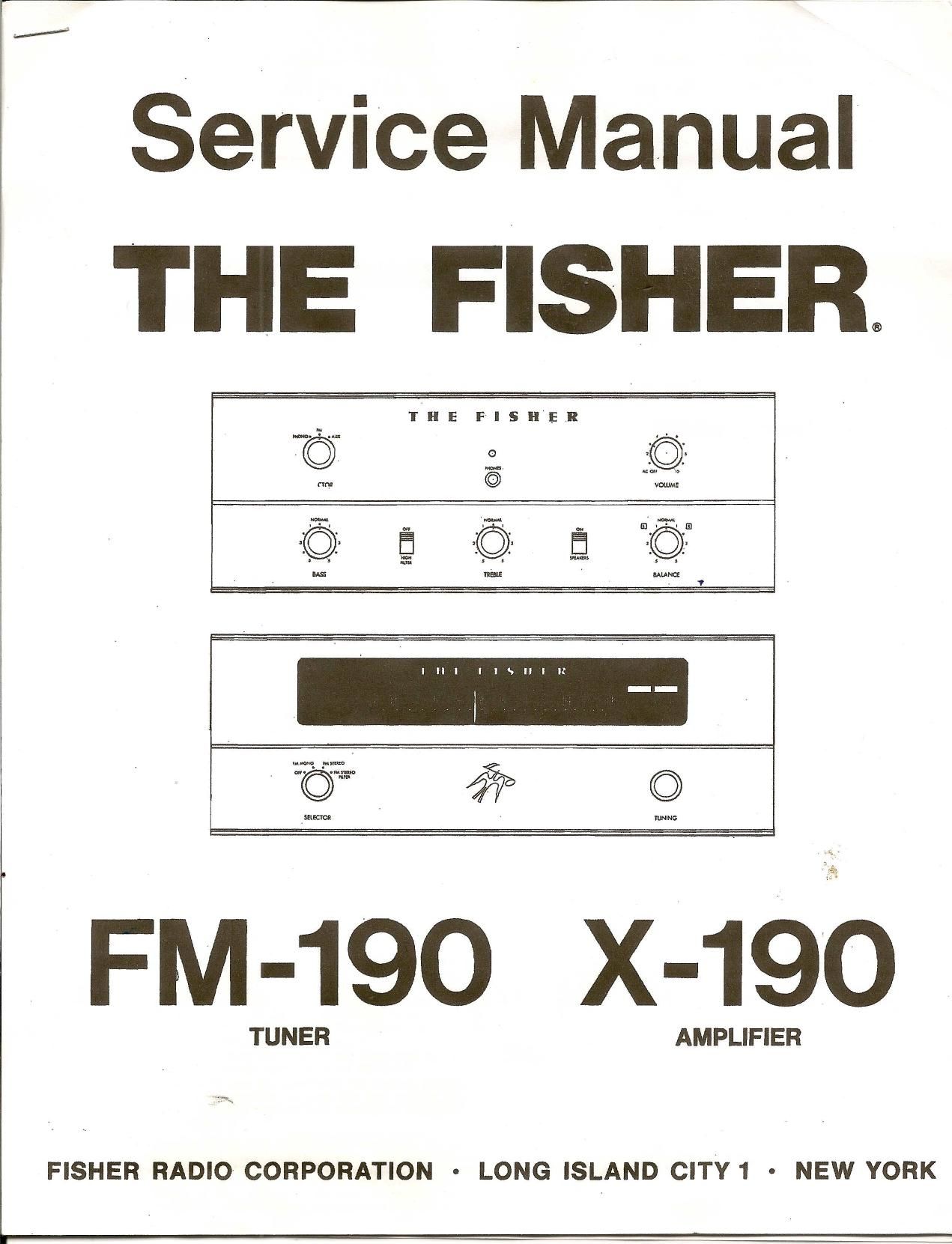
Fisher X 190 Service Manual

This is the 10 pages manual for Fisher X 190 Service Manual.
Read or download the pdf for free. If you want to contribute, please mail your pdfs to info@audioservicemanuals.com.

Page: 1 / 10
left right
Fisher X 190 Service Manual

Extracted text from Fisher X 190 Service Manual (Ocr-read)


Page 1

CAUT ION: ThisisaFISH ER precision high-fidelity in- strument. Itshould beserviced onlybyqualified personnel - trained inthe repair oftransistor equipment andprinted circuitry. EQUIPMENT ANDTOOLS NEEDED The following areneeded tocompletely testand align modern high-fidelity instruments such asamplifiers, tunersandreceivers. Miscellaneous Adjustable-line-Voltage Transformeror line-voltage regulator Load Resistors (2)-8-ohm, 50-watt(orhigher) Stereo source (Turntable withstereo cartridge or Tape Deck) Speakers (2)Full-range, forlistening tests Soldering iron(with small-diameter tip). Fully insulated frompower line. Test Instruments Vacuum-Tube Voltohmmeter DCVTVM Audio (AC)Vacuum-Tube Voltmeter(ACVTVM) Oscilloscope (FlattolOOkc minimum) Audio (Sine-wave) Generator I ntermodu lation AnaIyzer Sweep (FM)Generator (88to108 mc) Marker Generator Multiplex Generator (preferably withRFoutput- FISHER Model300orequal). Many ofthe items below areincluded justasare- minder- theyarenormal procedures, forexperienced technicians. Shortcutscanbetaken butoften they cause additional damage-to transistors, circuitcom- ponents orthe printed-circuit board. Soldering-A well-tinned,hot,clean soldering irontip will make iteasier tosolder without damage tothe printed-circuit boardorthe many manycircuit com- ponents mounted onit.Itis not thewattage ofthe iron that counts -itis the heat available atthe tip. Low-wattage solderingirpnswilloften taketoolong to heat aconnection -pigtail leadswillgettoohotand damage thepart. Toomuch heat,applied toolong, will damage theprinted-circuit board.Some50-watt irons reach temperatures of1,000° F- others willhardly melt solder. Small·diameter tipsshould beused for single solder connections -largerpyramidandchisel tips areneeded forlarger areas.' ' - When removing defective resistors,capacitors, etc., the leads should becut asclose tothe body ofthe circuit component aspossible. (Ifthe part isnot being returned forin-warranty factoryreplacement itmaybe cut inhalf -with diagonal-cutting pliers-to make removal easier.) - Special de-soldering tipletsaremade forunsolder- ing multiple-terminal unitslikeIFtransformers and electrolytic capacitors.Byunsoldering allterminals at the same timethepart canbe,removed withlittle chance ofbreaking theprinted-circuit board. - Always disconnect thechassis fromthepower line when soldering. Turningthepower switch OFFisnot enough. Power-line leakagepaths,through theheating element, candestroy transistors. Transistors-Never attempttodo any work onthe transistor amplifiers withoutfirstdisconnecting the - ~ AC-power linecord-wait until thepower supply filter- capacitors havedischarged. - Guard against shorts-ittakes onlyaninstant for a base-to-collector shorttodestroy thattransistor and possibly othersdirect-coupled toit.[In the time it takes foradropped machine screw,washer oreven the screwdriverrto glanceoffapair ofsocket terminals (or between aterminal andthechassis) atransistor can berllined.] - DO NOT biasthebase ofany transistor to,ornear, the same voltage appliedtoits collector. - DO NOT useanohmmeter fortesti ngtransistors. The voltage applied through thetest probes maybe higher thanthebase-emitter breakdownvoltageofthe transistor. Output StageandDriver-Replacements foroutput and driver transistors, ifnecessary, mustbemade from the same betagroup asthe original type.Thebeta group isindicated byacolored dotonthe mounting flange ofthe transistor. Besure toinclude thisin- formation, whenordering replacement transistors. - Ifone output transistor burnsout(open orshorts), always remove alloutput transistors inthat channel and check thebias adjustment, thecontrol andother parts inthe network withanohmmeter beforeinsert- ing anew transistor. Alloutput transistors inone channel willbedestroyed ifthe base-biasing circuit is open onthe emitter end. - When mounting a'replacement powertransistor be sure thebottom ofthe flange, themica insulator and the surface ofthe heat sinkarefree offoreign matter. Dust andgritcan prelent perfectcontact. Thisre- duces heattransfer tothe heat sink. Metallic particles can puncture theinsulator andcause shorts-ruining the transistor. - Silicone greasemustbeused between thetransist- or and themica insulator andbetween themica and the heat sinkforbest heatconduction. Heatisthe grea,test enemyofelectronic equipment. Itcan shorten the lifeoftransistors, capacitorsandresistors. (Use Dow-Corning DC-3orC20194 orequivalent compounds made forpower transistor heatconduction.) - Use care when making connections tospeakers and output terminals. Anyfrayed wireends cancause shorts thatmayburn outthe output transistors -they are direct-coupled tothe speakers. Thereisno output transformer -nothing tolimit current through thetran- sistors except thefuses. Toreduce thepossibility of shorts atthe speakers, lugsshould beused onthe exposed ends-at lea,st theends ofthe stranded wires should betinned toprevent frayedwireends. The current inthe speakers andoutput circuitry: isquite high. Anypoor contact orsmall-size wire,:,~~ncause power losses inthe speaker system.Use14ojl16 AWG for long runs ofspeaker-connecting wiring. DC-Voltage Measurements-These basictestsofthe transistor circuitryaremade without thesignal gener- ator. Without anysignal inputmeasure thecircuit volt- ages -as indicated onthe schematic. Thevoltage difference betweenthebase andtheemitter should be inthe millivolt range-asensitive DCmeter is needed forthese readings. Alow-voltage rangeof1volt, full scale -or lower -is needed. Audio-Voltage (gain)Measurements-The schematic and printed-circuit boardlayout diagrams areused. Input signals areinjected atthe proper points-found most quickly byusing layout ofthe printed-circuit board instead ofthe schematic. AnAUDIO (AC)VTVM connected tothe test points should indicate voltages close tothose values showninthe boxes onthe sche- matic. Manyotthe signal levelsinthe input stages are only afew millivolts-they cannotberead onthe AC ranges supplied onmost Vacuum-Tube AC/DCVolt· ohml!'eters (VTVMs). Evenwithal-volt range asignal level of100 millivolts (.1volt) willbethe first 1/10 of the meter scale.Areading of1millivolt (.001volt) will hardly evenmove themeter needle. '

Page 2

DIALSTRINGING PROCEDURE - Hook oneendofthe spring overthebottom eorinthe front --nd drive-drum (withthedrum rotated toits extreme counterclockwise position). - Stretch thetension springuntiltheloop onthe free end sticks outofthe slot inthe edge ofthe drive-drum. Now Insert alength ofstiff wire, about l-inch long (0 piece of straightened-out paperclipwill donicely) through theloop . to keep thespring stretched whilestringing thedial cord. Place thepiece ofstiff wire inthe outer groove ofthe drive-drumi bridgingtheslot inthe drive·drum. - Tie asmall, non-slip, loopinthe end ofthe dial cord. i Thread theloop inthe dial cord through theopening in the driveo/lrum slot,under thespring, andhook theloop over thetopear inside thedrive drum. - Wrap thedial cord around theclrive-drum (counterclock- wise) about * of aturn, inthe inner groove, ondthen around the top guide pulley. - Stretch thedial cord tothe left end ofthe dial, around th.nwo guidepulleys andthen back tothe fly-wheel drive shaft. - Wind 3full turns ofdial cord around the.drive shaft(as shown inthe upper detail drawing). - While keeping th"dial cord tautrotate thedrive-drum to TOINNEA~ GROOVE o TO OUTER GROOVE its extreme clockwise position andfitthe clioIcorcl into the remaining pulley. - Set thedial cord inthe outer groove ofthe front-end drive- drum andthread itthrough theloop inthe end ofthe tension spring. (Seedetail drawing.ot lowerright.) - Pull allslack dialcord through theloop inthe tension spring - - Check allpulleys forproper threading ofthe dial cord. - Tie asmall knotinthe dial cord tosecure it to the loop in the tension spring.(Useatweezer withasmall tipto help tiethe knot.) Keepdialcord astout aspossible while tying theknot. - Apply adrop ofquick-drying cementtothe knot toprevent it from slipping orbecoming undone. - After thecement hasdried completely pulloutthepiece of stiff wire andgently letthe spring contract t9~Q.pplytension to the dial cord. . ..':' . . :~. - Rotat. thefront·end drive-drum taits extreme'tbunter- clockwise position. - Set the clial pointer tothe zero (0)calibration onthe log- ging seale ofthe sIi de --.uIe cliol. - Attach.the pointertothe dial cord andcement itin place with adrop ortwo ofquick.dryin,ll cement. If replacement partsareout ofstock, locally, theymaybeobtained directly fromtheParts Department ofFIStlER RadioCorporation. They willbeshipped "bestway", either prepaid orC.O.D. unless otherwise specified. For instrument-operation informationandtechnical assistance write Richard Hamilton, CustomerServiceDepartment,FISHER Radio Corporation, LongIsland City,NewYork 11101.