Fisher X 100 Schematic

This is the 4 pages manual for Fisher X 100 Schematic.
Read or download the pdf for free. If you want to contribute, please mail your pdfs to info@audioservicemanuals.com.

Page: 1 / 4
left right
Fisher X 100 Schematic

Extracted text from Fisher X 100 Schematic (Ocr-read)


Page 1

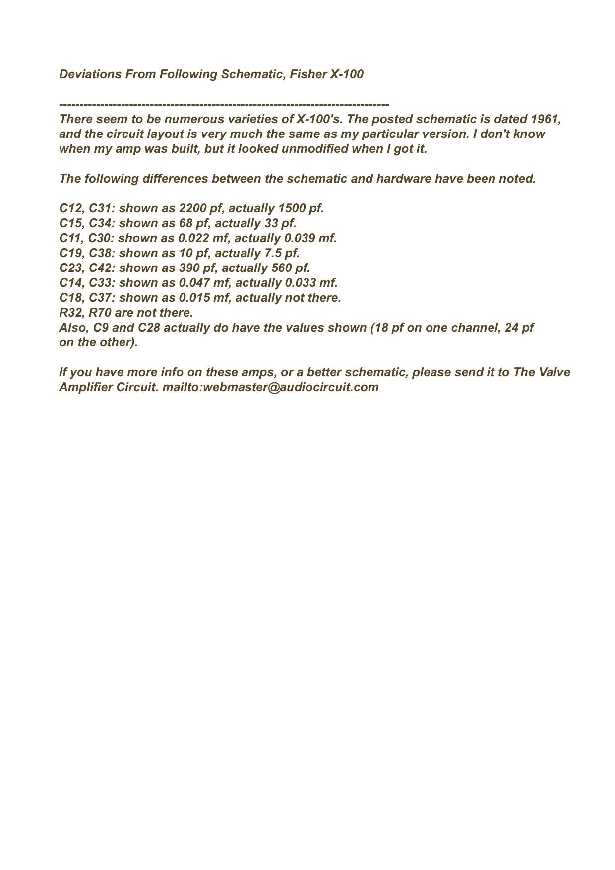
Deviations From Following Schematic, Fisher X-100

There seem to be numerous varieties of X-100's. The posted schematic is dated 1961,
and the circuit layout is very much the same as my particular version. ldon't know
when my amp was built, but it looked unmodified when I got it.

The following differences between the schematic and hardware have been noted.

C12, C31: shown as 2200 pf, actually 1500 pf.

C15, C34: shown as 68 pf, actually 33 pf.

C11, C30: shown as 0.022 mf, actually 0.039 mf.

C19, C38: shown as 10 pf, actually 7.5 pf.

C23, C42: shown as 390 pf, actually 560 pf.

C14, C33: shown as 0.047 mf, actually 0.033 mf.

C18, C37: shown as 0.015 mf, actually not there.

R32, R70 are not there.

Also, 09 and 028 actually do have the values shown (18 pf on one channel, 24 pf
on the other).

If you have more info on these amps, ora better schematic, please send it to The Valve
Amplifier Circuit. mailto:webmaster@audiocircuit.com