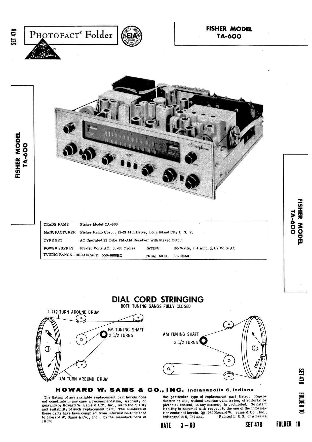
Fisher TA 600 Service Manual

This is the 16 pages manual for Fisher TA 600 Service Manual.
Read or download the pdf for free. If you want to contribute, please mail your pdfs to info@audioservicemanuals.com.

Page: 1 / 16
left right
Fisher TA 600 Service Manual

Extracted text from Fisher TA 600 Service Manual (Ocr-read)


Page 1

SH 475

PHOTOFACT® FolJer TA-bOO

FISHER MODEL
TA-bOO

FISHER MODEL

-_ TRADE NAME Flsher Model TA-600

MANUFACTURER Fisher Radio Corp. , 21-21 44th Dflve, Long Island Clly l, N. Y.

'1'va SET AC Operated 22 Tube FM powan SUPPLY 105-120 Volts AC, so-ao Cycles RATING 165 Wang, 1. «1 Amp. @117 Volts AC
TUNING RANGE-BROADCAST 550-1eooxc FREQ, MOD. BG-lOBMC

DIAL CORD STRINGING

BOTH TUNING GANGS FULLY CLOSED
1 1/2 TURN AROUND DRUM

AM TUNING SHAFT
2 1/2 TURNS

HOWARD W. SIMS a. 00.. INC. lndlanapolls 6.Indlana

The llntlng of any nvnllable replacement part nereln does the particular lype 01 replacement pan llsted1 Repro-
nol commute ln any case a recommendnuon, warranty or ductlon or use, wmmut express permissmnI of edltorlal or
guarmtyby Howard W. Sams S: Ctr, Inc,, as tn the quallty plcmrlal content, ln any manner, ls prohibited, No patent
and sultablllty 01 such replacement pan The numbers of llablmy ls assumed with respect tn the use of the Worm:-
mese parts have been complled from lnlqrmatlon furnished Mon conumed hereln © 1960 Howard W, Same 51 C01 , Inc. ,
to Howard We Sims & Co. , l.nc,, by the manufackurers of lndlanapolis 6, lndlana, Prlnted in U15, 0! Amerlca
(620

DATE 3- Bl]

SET 478

FOLDER

009V1
HGOW HIHSII

I

[ll lllll'lfll BUHS

Page 2

ALIGNMENT INSTRUCTIONS

ALIGNMENT INSTRUCTIONS-READ CAREFULLY BEFORE ATTEMPTING ALIGNMENT

output reading.
Suggested alignmen

AM Bandwidth set t

Volume control should be at maximum position. Output of signal generator should be no higher than necessary to obtain an

t tools: Al film A4, A6, A10 thru A14. . .. GENERAL CEMENT 5097, 8727
WALSCO #2515

A5, A15, thru A19 .............. GENERAL CEMENT 08606, 86061., 8282, 9295
WALSCO 92526, 2543, 2544, 2545

A7, A8, A9 .................... GENERAL CEMENT #5004, 5008, 5009
WALsco «2520

A20, A21, A22 .................. GENERAL CEMENT #8271,5273,8275,8276,8721,8722,9150,
9298, 5003

WAISCO #2516, 2519

AM ALIGNMENT - SELECTOR IN AM POSITION

o SHARP.

Short point ® to chassis. Remove short when AM alignment is completed.

SIGNAL SIGNAL RADIO
GENERATOR GENERATOR DIAL CONNECT ADJUST REMARKS
COUPLING FREQUENCY SETTING VTVM

High side thru .Olmid 455KC (AM) AC probe to Al, A2, Adjust for maximum deflection.

to pin 2 (grid) of AM (400% Mod.) Point of non- channel "A" A3, A4

Mixer. Low side to interference RCEJR out-

chassis. put. Low
side to chas-
SIS.

" 455KC " Use Scope. Switch bandwidth to broad. Retouch A3
(SOKC Swp) Vert. amp. SLIGHTLY for symmetrical response.

to channel Switch bandwidth back to sharp.
"A" RCRDR
output. Low
side to chas-
sis.

High side thru 220nm GOOKC GDOKC AC probe to A5, A6 Adjust for maximum deflection.

to AM antenna termin (400i: Mud.) channel "A"

a1 *3. (Disconnect RCRDR out»

link between terminal put. Commor

l and 2.) to chassis.

MOOKC I400KC " A7, A8, Adjust for maximum deflection. Repeat

A9 Steps 8 and 4.

FM IF ALIGNME

NT USING AM SIGNAL GENERATOR AND VTVM-SELECTOR IN FM POSITION

alignment point

Connect two "13% 100K (11%) resistors in series from point @to chassis. The junction of these two resistors is

as shown on the schematic.

SIGNAL SIGNAL RADIO
GENERATOR GENERATOR DIAL CONNECT ADJUST REMARKS
COUPLING FREQUENCY SETTING VTVM
High side to un- 10. 7MC (FM) DC pro to A10,All, Adjust for maidmum deflection.
grounded tube shield (Unmod.) Point of non- point . A12, A13,
floating over FM interference Common to A14, A15

Mixer-Osc. Low chassis.
side to chassis.
" " DC pr to A16 Adjust for zero reading. A posItive and
point . negative reading will be obtained on either
Comm n to side of the correct setting,
point .

FM IF ALIGNMENT USING FM SIGNAL GENERATOR AND OSCILLOSCOPE-SELECTOR LN FM POSITION

Use frequency modulated signal with 60m modulation and 4501(0 sweep. Use 12m sawtooth voltage in scope for
horizontal deflection.

SIGNAL SIGNAL RADIo CONNECT
GENERATOR GENERAIOR DIAL ADJUST REMARKS
COUPLING FREQUENCY SETTING SCOPE
High side to un- 10, IMC (FM) Vert. A . A10,Al1, Disconnect Stabilizing capacitor Cd. Adjust
grounded tube shield (450KC Swp) Point on non- to point$ . A12,A13, for maximum gain and symmetry of response
floating over FM interference. Low side 0 A14,A15 similar to Fig. l Reconnect C4.
Mixer-Osc. Low chassis.
side to chassis.
" " " Vert. am . A16 Adjust to place marker at the center of cross-
' to point é . over lines similar to Fig. 2. SLIGHTLY
Low side 0 retouch A15 for maximum amplitude and
chassis. straightness oi crossover lines.
FM RF ALIGNMENT -- SELECTOR IN FM POSITION
SIGNAL SIGNAL RADIO
GENERATOR GENERATOR DIAL Cfifiyf, ADJUST REMARKS
COUPLING FREQUENCY SETTING
Across FM antenna SOMC I (FM) DC pro e to A17,A18, Adjust for maximum deflection,
terminals 5 (I 6 with QDMC point . A19
120i) in each lead. Common to
chassis.
" IOGMC IOBMC " A20,A21, Adjust for maximum deflection. Repeat

A22, Steps 7 and 8.

IO.7MC

FIG. I
10.7MC

FIG. 2