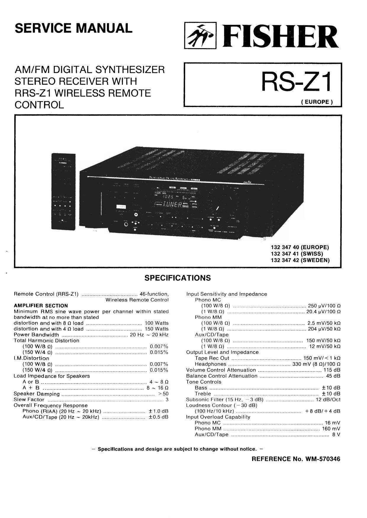
Fisher RS Z1 Service Manual

This is the 38 pages manual for Fisher RS Z1 Service Manual.
Read or download the pdf for free. If you want to contribute, please mail your pdfs to info@audioservicemanuals.com.

Page: 1 / 38
left right
Fisher RS Z1 Service Manual

Extracted text from Fisher RS Z1 Service Manual (Ocr-read)


Page 1

SERVICE MANUAL

AM/FM DIGITAL SYNTHESIZER
STEREO RECEIVER WITH
RRS-Z1 WIRELESS REMOTE
CONTROL

FISHER

RS-Zi

(EUROPE)

132 347 40 (EUROPE)
132 347 41 (SWISS)
132 347 42 (SWEDEN)


SPECIFICATIONS
Remote Control (HRS-21) .................................... 46~function. Input Sensitivity and Impedance
Wireless Remote Control Phono MC
AMPLIFIER SECTION (100 W/8 Q) .. 250 (JV/100 Q
Minimum RMS sine wave power per channel within stated (1 W/B Q) .2014 uV/1OO Q
bandwidth at no more than stated Phone MM
distortion and with 8 0 load . .i 100 Watts (100 W/B fl] . 215 mV/SO k0
distortion and with 4 0 load .. 150 Watts (1 W/B (1) ..... H 204 LIV/50 k0
Power Bandwidth ,, 20 Hz ~ 20 kHz Aux/CD/Tape
Total Harmonic Distor Ion (100 W/8 n) 150 mV/50 k0
(100 Wit; 0) .. 0.007% (1 W/8 0) , 12 mV/SO km
(150 WM 0) . 0.015% Output Level and Impedance
l.M.Distortion Tape Rec Out . .. 150 mV/<1 kn
(100 W/8 n) .. 0.007% Headphones 0 mV (8 Q)/100 n
(150 WM 0) . 0.015% Volume Control Attenuation 115 dB
Load Impedance for Speakers Balance Control Attenuation . . 45 dB
A or B .. 4 ~ 8 (1 Tone Controls
A+B .. 8~160 Bass... .i10dB
Speaker Damping . >50 Treble . :10 dB
Slew Factor . 3 Subsonic Fllter (15 H7, 3 dB) . 12 018/061
Overall Frequency Response Loudness Contour (*30 dB)
Phono (RIAA) (20 Hz ~ 20 kHZ) . 1-1.0 dB (100 Hz/10 kHz) .......................................... +8 dBl+4 dB
Aux/CD/Tape (20 Hz ~ 20kHz) , $0.5 dB Input Overload Capability
Phono MC ............................................................. 16 mV
Phono MM ...... 160 mV
Aux/CD/Tape , ..... 8 V

- Specifications and design are subject to change without notice -

REFERENCE No. WM-570346

Page 2

SPECIFICATIONS (Comlnued)

Signal-MOI" Ratio (IMF. A-Nelwont)

3:22: mg E220 Note to elm-I unnooueery to odluet coll In Front End n portectly actuated.
créggsugfic 0 m ) To. Harmonie ammo" (59 am ITEM GENERATOR DIAL sET'nno INDICATOR PROCEDURE
2 1 WM (00 I kHz/6 Ill 1. FRONT END Do not connect Front Panel Connect DI: Volt- Aoiust FM 050 Coll (L507) untll
:ztwee: :flcemsum Chnnnols 75 as 5' 3;?(1'60 Hm k cosmos/0.1% FREQUENCY generator. DIGITAL counter meter to TP512 no Voltmeter roeos 25.0v 20.2w.
m o' I I a
Speaker: Selector , , 3. OFF wtoe .. aunt/0.1% iaéi'llsm sellguwnz. fighting? 5
1Dllpley . . FL WIth Seton Dimmer Stereo Super-titan (108MHz)
liner some minutes Wide too Hz/t kHz/10 kHz .. lo /
Auolo Mutlng ,_ -5g OI Capture Am, 5 5 35 dB 2, Same IS above. DIGITAL Counter Same as above. Check DC voltmeter lor lndicallon
sol-arm. 35mm wm. 13 as (875MHz) gem; 5M 3.5v ~ my.
M "II requancy . 32144.11 Iutz Narrow 5,0 as 9' '0 4 L
D" °°""°"'°" "9 1" L'm' WWW! Note: nope-t tho adlustmems in Items I and 2. Then. conlirm that each voltege becomes ow to 25W It receiving Irequency
lanOutput Terminols 2 DM convene I ' m as °' 375 w mm"
arrow
on Input Imaoe Response a. a 13:: 3. FM RF ConneoI Spectrum DIGITAL Counter Connect Spectrum Adjust FM ANT Coll (L503) and
Aux (Front/Ron) Input . , swims (spam Rm, 120 as TRACKING analyzer (with FM RF Display analyzer Input to FM RF ooil [L504 ~ L506)
DAT Input/Output Optiul IF Response Ratlo 120 dB ALIGNMENT Tracking generator) Set to sanMHz. TP501 and ground so thet S-wave from becomes
Optic-l Input - 15 item ~ -24 dam AM Suppression Ratio . so at: (SBDMHz) output to FM Antenna lean to Chassis. symmetrical.
Dolley! Output - t5 dam - -2t dBrrI Audlo Frequency noeponee WINK
CoaxIal Input . 500 mVVpnlt o 120% (20 Hz . 15 kHz) 15 dB Set generator to 58.0MH1.
Ftlters B-IlmesVOversampllnq Dlgltll Filter. Sub-Carrier Relocuon (19 IrI-Iuaa kHz) . 80/90 on "m m" 1? 9
an] Order Llnonr Phase Low Pm Filter Stereo Threshold i. 1917 55) provide 2Ml-tz devtatIon.
Frequency Response (20 Hz ~ 20 kHz) AM SECTION Settlng generator
Signal-twain Rum Tuning Range , . 522 kHz ~ ten kHz W'm 6"3" 9'
$333M 956 n_ (1 kHz) IHF Usable Sensitivity We' '0! NEW-
Armonlc Is 0 Ion External Antenna Chan ' *
. ge generator Change DIGITAL Same as above. Adjust FM ANT Trimmer (T0501) and
cum 93mm" (1 '1 LOW! Antenna »- (103MH1) Setting to 103MHz. Counter Display FM FIF Trimmer (76502 40504)

FM SECTION
Tuning Range .
Antenna Terminals
Usable Sensltlvity
Mono

Total Harmonic Dlslorllon (45 as uuieting)


Signal Seeker Stop Sansltlvtty
SignaIFtoNoise Flatlo
Image Response Hallo
IF Response Ratio .
Selectlvtty (19 kHz) .

FM TUNER ALIGNMENT

FM ALIGNMENT - Band Selector switch to FM/ST(MUTE) position.

Set to 108MHz.

so that S-weve Irom becomes
Symmetrical.

Non: Repeal Ihe adjustmenfi in Items 3 Ind 4. Then, confirm there Is no tracking error.

5. REFERENCE

Change generator

change DIGITAL

Connect Frequenc

Adjust PLL OSC Trimmer (T0506) 09

Stereo Volume Sensitivity ~ »
. PLL 05C Settlng to DSMHI. Counter Dlsplay Counter to TP511 "3507 LM7000 Slde) untII Frequency
6 d: 0 9 5' ""V TOW E'momc Woman ALIGNMENT Set to saMHz. and ground lead Counter reads IOBJOOMH: tlkHz.
one Frequency Response (- 3 dB) . lo Chesslso
_ Stereo _ > _ GENERAL _
Signal Seeker Stop Sonsmwty , Power Requirements AC 220V 6 FM CENTER Same as above. Adyust Same as above. Connect DC Volt- Amust FM DET Coll (T511) until
SIanal-IoNaise Ratio (50 Hz) . . 400 Watts VOLTAGE attanuotor output level to meter across DC Voltmeter reads 0V tZOmV.
Mono Ac 0mm, 3 (DETECTOR) mauv (IliIIz, WkHz rpsm eno TP505.
Stereo DIMBMIOHS (WxHxD) 480 x 165 x Dom ALIGNMENT deviation) [MONO Mode.
Welsh! (apF'DX-l 21kg 7. FM MUTING Set generntor to MMHz. Same es above. Front panel Set Mode Switch to sT(MuTE).
AUTO STOP Adluet motivator output TUNED Indicator Adjust vnsua until the TUNED
.- Soocmcotlono and design Ira eublod Io chem wllhom flange, - iggagmgn level to tmeuv. Display. Indicator partly light up.

Home: Decrease the output level (ToofiuVl m ATT Ind eonlirm that the wave lorm disappears. Increase the output level
(Maw) 07 ATT ngein and confirm that the input level meets the specifications eutliclently when the wove term has up-

neared.

8, FM CENTER Same as above. Same as above. Connect DC Volt- Ad)usl FM DET (1) Coil (T506) until
VOLTAGE Adiusl attenuator Output meter across DC voltmeter rem: 0V tfiUmV.
ALIGNMENT level to WBuV TPSDB Ind TP509.

IMONO Mode.

9. DETECTOR Same as above. Same as above. Connect Hormontc Adjust FM DET (2) Call (T507) and
ALIGNMENT [IF BAND Switch to WIDE) Distortion FM lFT Coil (T5034T504) Ior
(MINIMUM Analyzer to Audlo minlmum gain and best Iinearin.
T.HiD.) OUIOUI (CNIOE).

Not . spell 3180 3 (FM BET 1 Coil T506) and 9 (FM DET 2 Coil T507 and FM IFT coil T503, T504) until Optimum alignment is

reached

10 DETECTOR Same as above. Same as lbove, Same as above. Adjust FM IFT (T504, T505) Ior
ALIGNMENT (Change IF BAND Switch Set Tuning minimum pain and best linearity
(MINIMUM to NARROW) Switch to (AUTO)

T.HID.) Modulate with IOOHZ ON position.

Stereo Signal (L-R).

Noun: Set the Modulate Signal oI the FM stereo signal so to 5 kHz (LA R) and mnke sure Ihatthe Distortion Analyzer inotcerore
within the spectltoetions. (II the distortion level at 100 Hz is wrong, must 0509)
When adlustlng. do not touch the FM DET (1)ccul (T506) and FM DET (2) coll (T507) aoiueteo in step 8 end 9

-3-