Fisher RS 1040 Service Manual

This is the 20 pages manual for Fisher RS 1040 Service Manual.
Read or download the pdf for free. If you want to contribute, please mail your pdfs to info@audioservicemanuals.com.

Page: 1 / 20
left right
Fisher RS 1040 Service Manual

Extracted text from Fisher RS 1040 Service Manual (Ocr-read)


Page 1

gram;

.rnodulnr Esfi=§i somponenwm

Pages 13.,32 Courtesy of FISHER RADIO CORP.
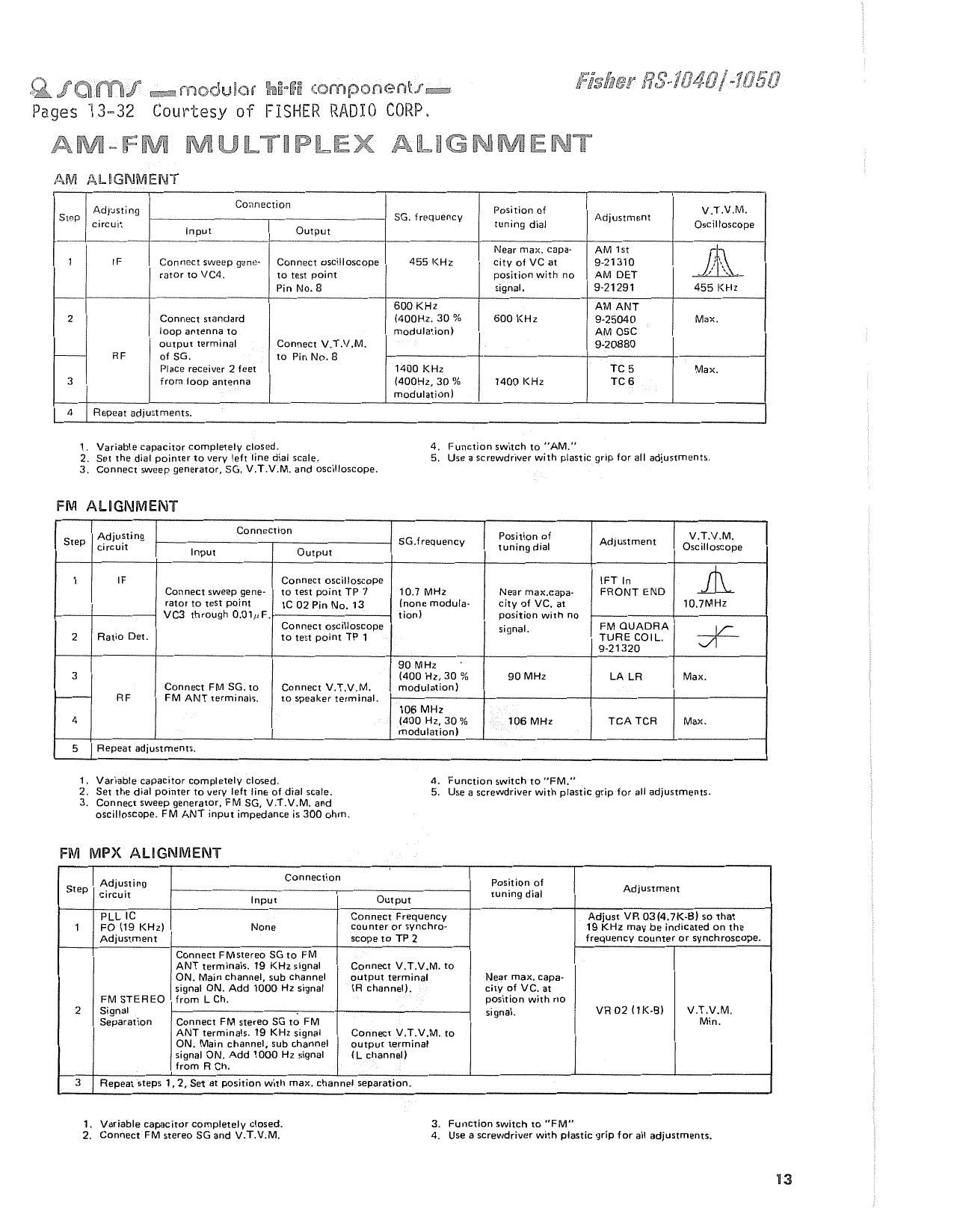
AMeFM MULTHPLEX ALIGNMENT

AM ALlGNMENT

Fisiaer fig-754W 1785i?

. . Connection . .
Step Aduilmg _ SG. lrequencv Position .Of Adjustment VT'VM'
circun tuning dial Oscilloscope
Input Output
Near max. caoa AM Ist I
1 IF Connect sweep gene- Connect oscilloscope 455 KHz city of VC at 9-21310 AK
rator to VGA. to test point position with no AM DET »
Pin No. 8 signal. 921291 455 KHI
600 KHz AM ANT
2 Connect standard (ADDHZ, 30 % 600 KHZ 9-25040 Max.
loup antenna to modulation) AM OSC
output terminal Connect V.T.VsM. 940880
RF of 5G. to Pin No. a
Place receiver 2 feet 1400 KHz TC 5 Max.
3 from loop antenna MODHZ, 30 Vc MOD KHz TC 6
modulation)
4 Repeat adjustments.

1 .

Variable capacitor completely closed
2. Set the dial pointerto very left line dial scale.
3. ConneCt sweep generator, SG, V.T.V.M. and oscilloscope.

FM ALIGNMENT

4. FunCtion switch to "AM"
5. Use a screwdriver with plastic grip for all adjustments.

. . Connection . .
Adjusting Position pl . V.T.V.M.
529 circuit Inpm 0mm 55"'eq°°" tuning dial WSW? Oscilloscope
1 IF Connect oscilloscope IFT In l 5
Connect sweep gene» to test point TP 7 10.7 MHz Near maxccapav FRONT END
rator to test point It: 02 pin No. 13 (none mudula- city of VC. at 10.7MH2
V03 through 0.01pF. tion) position With no
Connect oscilloscope signa. FM OUADHA
2 Ratio Det. to test point TPI TURE COIL. 74
9-21320
90 MHz
3 (400 Hz, 30 A: 90 MHz LA LR Max,
Connect FM 86. to Connect V,T,V.M, modulation)
RF FM ANT terminals, to speaker terminals
105 MHz
4 (400 Hz, 3D 96 105 MHz TCA TCFI Max,
modulationl
5 Repeat adjustments
1. Variable capacitor completely closed. 4, Function switch to "FM."
2. Set the dial pointer to very Ielt line of dial scale. 5. Use a screwdriver with plastic grip for all adjustments.
3. Connect sweep generator, FM 56, V.T.V.M. and

oscilloscope. FM ANT input impedance is 300 ohm.

FM MPX ALIGNMENT

. . Connection . -
3933?? 5mm
Input Output
PLL lC Connect Frequency Adjust VR 03l4.7K-B) so that
1 F0 (19 KHz) None counter or svnchre- 19 KHz may be indicated on the
Adjustment scope to TP 2 frequency counter or synchroscope.
Connect FMstereo SE to FM
ANT terminals. 19 KHz signal Connect V,T.V,M. to
ON. Main channel, sub channel output terminal Near max, capa<
signal 0N. Add 1000 Hz signal lFI channel). city 0' VC. at
FM STEREO from L Ch. position with no
2 Signal . signal. VFlOZ (H93) V.T.V.M.
Separation Connect FM stereo 5G to FM Min.
ANT terminals. 19 KHz signal Connect V.T.V.Mc to
ON. Main channel, sub channel output terminal
signal 0N. Add 1000 Hz signal (L channel)
from R Ch.
3 Repeat steps 1, 2,5et at position with max, channel separation.

Variable capa

citor completely closed.

2. Connect FM stereo SG and VcT,V.M,

3. Function switch to "FM"
4. Use a screwdriver with plastic grip for all adjustments.

I3