Fisher RS 1015 Service Manual

This is the 24 pages manual for Fisher RS 1015 Service Manual.
Read or download the pdf for free. If you want to contribute, please mail your pdfs to info@audioservicemanuals.com.

Page: 1 / 24
left right
Fisher RS 1015 Service Manual

Extracted text from Fisher RS 1015 Service Manual (Ocr-read)


Page 1

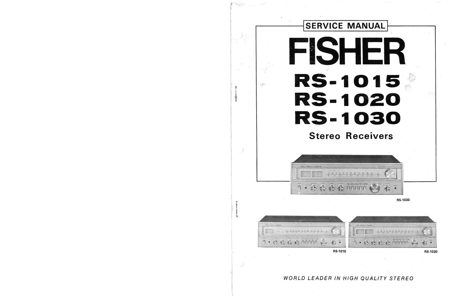
SERVICE MANUAL

i FlSHER

RS- 1 o 1 5
RS- 1 020
RS- 1 030

Stereo Receivers

RS-1030

RS-1015 RS-1020

WORLD LEADER IN HIGH QUALITY STEREO

Page 2

i
t
r
;

TABLE OF CONTENTS

Disassembly instructions ............................................................... 3
Recommended Test Equipment ......................................................... . .4
Harmonic Distortion Test .............................................................. 4
Specifications ...................................................................... 5
AM»FM Multiplex Alignment ........................................................... 6
Aiignment Wave Forms ............................................................... 7
AM-FM RF/lF MPX Board Layout ....................................................... 7
Dial Cord Stringing .................................................................. 8
AMxFM RF/IF MPX P.C. Board ...................................................... 9,10
RF. IF. MPX P.C.B Assy Parts List ...................................................... 11
FM IF IC LA1230 Signal Flow ........................................................ 12
FM MPX lC LA3350 Signal Flow ...................................................... 12
AM RF IF iC HA1151 Signal Flow ..................................................... 12
Tone Control and Mode Selector P.C. Board .............................................. 13, 14
Tone P.C.B. Assy Parts List ........................................................... 15
E0 P.C. Board .................................................................... 16
E0 P.C.B Assy Parts List ............................................................ 16
Power Amp P.C. Board ............................................................ 17,18
Power Amp iC Equivalent Circuit ....................................................... 17
Power Amp P.C.B Assy Parts List ....................................................... 18
Power Supply P.C. Board ............................................................. 19
Dial Lamp P.C. Board ................................................................ 19
Power Supply P.C.B Assy and Dial Lamp P.C.B Assv Parts List ................................... 20

Exploded View of Cabinet
and Chassis Front Mounted Assemblies (RS-1015) ............................................ 21
(RS-1020) ............................................ 25
(RS-1030) ............................................ 29

Exploded View of Chassis
and Rear Mounted Assemblies (RS-1015) .................................................. 22
(RS4020) .................................................. 26
(RS-1030) .................................................. 3O
Schematic Diagram (RS-1015) ...................................................... 23, 24
(RS-1020) ...................................................... 27,28
(RS-1030) ...................................................... 31 , 32
Parts List (RS-1015,RS-1020,RS-1030) .................................................... 33
Misc Parts List {RS-1015, RS-iOZO, PIS-1030) ................................................ 34
Point to Point Wiring Diagram Top View (RS-1015) ......................................... 35, 36
(RSV102O, RS-iOSO) .................................. 39, 40
Point to PointWiring Diagram Bottom View (RS-1015i ...................................... 37, 38
(RS»1020,RS-1030) ............................... 41,42

_2__

mm, w

2 7,23 m

new

Page 23

NOTES

31%. win,

23...

hey

, _ . :»,,§,,5.§i_:.2_, :,

-43_