Fisher RK 1 Owners Manual

This is the 2 pages manual for Fisher RK 1 Owners Manual.
Read or download the pdf for free. If you want to contribute, please mail your pdfs to info@audioservicemanuals.com.

Page: 1 / 2
left right
Fisher RK 1 Owners Manual

Extracted text from Fisher RK 1 Owners Manual (Ocr-read)


Page 1

FISHER RADIO CORPORATION

Pan Na. N»7AA-I06

NEW YORK

an Ram-I II

INSTALLATION AND OPERATING
INSTRUCTIONS

FISHER MODEL RK-I
REMOTE CONTROL

For Use With 400-C Master Audio Control

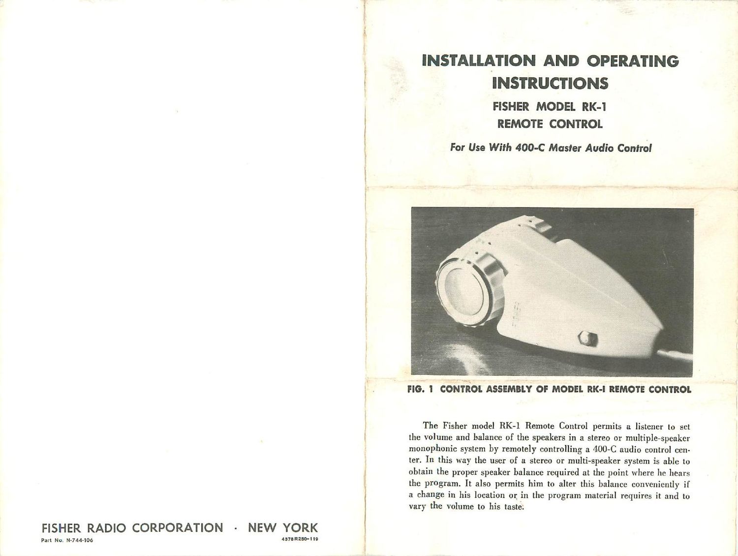
no. 'I eoufiim ASSEMBLY or moon. RK-l nmor: corneal.

The Fisher model RK-l Remote Control permits a listener to set
the volume and balance of the speakers in a stereo or multiple-speaker
monophonic system by remotely controlling a 4-OO-C audio control cen-
ter. In this way the user of a stereo or multi-speaker system is able to
obtain the proper speaker balance required at the point where he hears
the program. It also permits him to alter this balance conveniently if
a change in his location or in the program material requires it and to
vary the volume to his taste;

Page 2

TAPE MONITORS OUTPUTS INPUTS
l l l- -l

CHANNEL A CHANNEL B MAIN RC RDR (TOP)

(REAR)

i; Q | E; CHANNEL A J
A Law
BLACK

CHANNEL 3 -J


wHITE
ITEAIt PANEL 400-: CONTROL
BLUE ADAPTOR PLUG
CONNECTING CABLE
CHANNEL A
TO
CHAN

ON 7 "51 a

4P5 RECORDER FIG. 2 CONNECTIONS TO 400-: CONTKO

AND TO TAPE RECORDR

DESCRIPTION

The RK-I Remote Control consists of a control assembly, 30 feet
of connecting cable and an adaptor plug assembly for connection to
the 400-C Master Control. The control assembly (see Fig. l) is a plas-
tic ivory case with two knobs, each of which controls the level in one
of the speaker channels. The control assembly is held in one hand and
its knobs rotated with the thumb or index finger.

\W-1597

I.

INSTALLATION

To install the RK~1 Remote Control into your present system. proceed
as follows:
l-Turn oil' the power in your 400-C audio control by turning the
Volume control t'ully counterclockwise.
2 ~-- Connect the adaptor plug to the rear panel of the 400-C as shown
in Fig. 2. Plug 1 (blue) goes to Channel A ucnnn OUTPUT, Ilug 2 (red)
to Channel A TAPE MONITOR, Plug 3 (while) to Channel B RCItDlK OUTPUT
and Plug 4 (black) to Channel l3 TAPE MONITOR.

3-H your system includes a stereo tape recorder. connect Jack 5
(blue) to the cable from the Channel A input jack on your recorder
and Jack 6 (white) to the Channel D input cable.

4- Connect the nine-pin plug on the connecting cable to the mating
jack on the adaptor plu".

S-Unwind the cable and place the control assembly on a table top
or arm chair at a convenient point within the prime stereo listening urea.
6-Turn both knobs in the direction away from you to maximum
position.

7 -Set the Volume control on the 400-C to a position which is some-
what louder than desired for normal listening. This determines the
maximum level to which the RK-l Remote Control will operate.

8 - Set the Output Selector on the 400-C to STANDARD STEREO.

OPERATION

The remote control is operated with the gold dots on the plastic
assembly facing the user as shown in Fig. I. In this position, the knob
on the left controls the level heard in the speakers to the listeners left.
and the right knob regulates the volume in the speakers at the right,
providing the Output Selector on the 400-C is set to STANDARD sreneo.
This is reversed if the master control is set to REVERSE sranso.

When the gold dot on the knob lines up with the gold dot on the
case, the level in the channel which the knob controls is zero. Turning
either knob from this position, in the direction away from the user,
raises the level. Turning the knob in the other direction, reduces it.

After the RK-l has been installed. turn on your 4-00-C and listen
to any program material. Rotate each knob on the remote control until
the desired level is heard in each speaker and the proper balance is
obtained between them. Adjust these knobs accordingly whenever sub-
sequent program material alters the channel balance you have estab-
lished, or if you wish to vary the volume.

Note that when the gold dots on the knobs coincide with the gold
dots on the case of the remote control unit. there is no output from
your 400-C. Turning the knob to this position, therefore, permits you
to use the RK-l as a switch to cut oil either the Channel A or Channel B
output with the 400-C still on. Do not forget to turn the 400-C off after
you are through using the system.