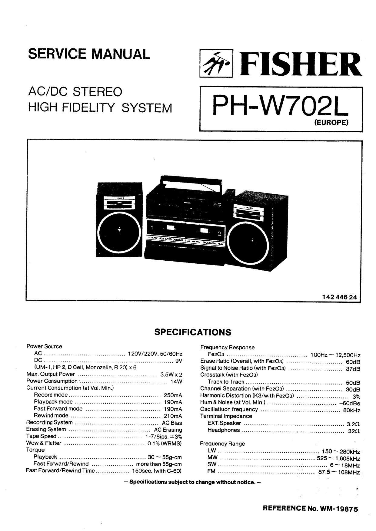
Fisher PHW 702 L Service Manual

This is the 18 pages manual for Fisher PHW 702 L Service Manual.
Read or download the pdf for free. If you want to contribute, please mail your pdfs to info@audioservicemanuals.com.

Page: 1 / 18
left right
Fisher PHW 702 L Service Manual

Extracted text from Fisher PHW 702 L Service Manual (Ocr-read)


Page 1

SERVICE MANUAL

AC/DC STEREO
HIGH FIDELITY SYSTEM

FISHER

PH-W702L


(EUROPE)
1 42 446 24
SPECIFICATIONS
Power Source Frequency Response
AC ............................... 120V/220V, 50/60Hz FeeOa ...................................... IDOHz ~ 12,500Hz
............................... 9V EraseRalio (Overall, with Fean) .. SOdB
(UM-1. HP 2, D ell, Monoze e, R 20) x 6 Signal to Noise Ratio (with Fe203) .......................... 37dB
Max. Output Power .................................... 3.5W x 2 Crosstalk (with Fe203)
Power Consumption ...... 14W Track to Track ............................... .. 50dB
Current Consumption (at Vol. Min.) Channel Separation (with FezO .. SOdB
Record mode ................................ 250mA Harmonic Distortion (KS/with F8203) ..... 3%
Playback mode . 190mA Hum & Noise (atVol. Min.) ........... -60st
Fast Forward mode .................................... 190mA Oscillatiuon frequency . ................................ 60kHz
Rewind mode ........................................... 21 OmA Terminal Impedance
Recording System . AC Bias EXT.Speaker ................................................ 3.20
Erasing System .. AC Erasing Headphones ................................................. 32a
Tape Speed ........................................ 1-7/8ips, i3%
Wow 8. Flutter ...................................... 0.1% (WRMS) Frequency Range
Torque LW ........................................ 150 ~ 2BOkHz
Playback ......................................... 30 ~ 559-cm MW .. ............... 525 ~ 1,605kHz
Fast Forward/Rewind . . more than 559-cm SW ............................. 6 ~ 18MH2
Fast Fomard/Rewlnd Time ......... . 150sec. (with C-60) FM .................................... 87.5 ~ 108MHz
- Specifications subject to change without notice. -

REFERENCE No. WM-1 9875

Page 2

CABINET PARTS LIST

:3? Part No. Description O'ty 533' Part No. Description Oty
PACKAGE P083 141-0-1939-22331 Power P.C.B. Assy 1
141-6-1419-86520 lndvidual Carton 1 P054 141 01939-22351 Graphic Equalizer PCB. Assy 1
141 45-14694 5700 Case Styroloam Top 1 P085 141-0-1939-22340 Control PCB. Assy 1
141 64469-15000 Case Styroloam Bottom 1
141 -6-2519-21390 Poly Cover 1 0X1 620-3-0910-00000 String, d>05 1
141-6-2519-21490 Poly Cover 2 0X2 411 040 4604 $08 PAN 2.6XE 1
141-6455903201 Serial No Sheet 2 0X3 411 040 4802 SCR PAN 2.6)(8 1

0X4 411 002 9104 SCR PAN 3X8 1
0X5 411 023 3303 SCH SvTPG PAN 2.6X8 1
ACCESSORIES CXG 411 0231002 SCR S-TPG PAN 2.6X10 1
131 -6-271 9-10401 Bag Fan 1 0X7 411 023 4003 SCR S-TPG PAN 3X10 9
141-6-4729-07400 Laoel Caution 1 0X8 411 023 4201 SCR 5»TPG PAN 3X10 1
141-6-4729-07700 Label Caution 1 0X9 411 023 6304 SCH S-TPG PAN 3X20 4
142-6-4119-33485 instruction Manual 1 0X10 411 021 6405 SCH S-TPG BIN 3X8 2
Exit 411 000 9908 RING E 3 4
CX12 4110010102 RING E 4 1
CABINET
4-2359-79270 Socket Lug Wire Assy 1
42352-02694 Connector 2P Assy [CNS] 1 NOTE:

CA1 141 -0-1129-17824 Cabinet Bottom Assy 1 1. Parts order must contain Model Number. Part Number and

CA2 141-2-421 9-1240!) Screw 4 Description.

GAG 141-2421943400 Screw 1 2. Ordering quantity of screws and resistors must be multiple of

CA4 4-2449-70630 Rod Antenna 1 10 pcs.

CA5 141-2-1719-29900 Handle 1

CA6 141-2-1339-37500 Lid Battery 1

CA7 141 40519-06700 Spring Cassette Case Lever B 1

CA8 141-2538905000 Drum Dial 1 PRODUCT SAFETY NOTICE

CA9 14112377940400 Home, PCB 2 Each precaution in this manual should be followed

cam 141 .2-1629-10800 Knob Lever 2 during servicing. Components identified with the IEC

CA11 141-2~7519-72800 ShaltDiaI t symbol A in the parts list and the schematic diagram

CA12 141 -2-4219-14000 Screw 2 designate components in which safety can be of special

ems 1.21551903300 none, Dial A 2 significance. When replacing a component identified

CA14 141.2.5119.134oo Pointer 1 with A, use only the replacement parts designated, or

CA15 141.2.4219.2zeoo Screw Poly Wave 3 parts with the same ratings of resistance, wattage or

cme 141 121375943700 Fix Card 1 voltage that are designated in the parts list in this manual.

CA17 A 4.2439.72790 pawerCmd 1 Leakage-current or resistance measurements must be

CA18 141-2-3229-57200 Shield Plate 1 made to determine that exposed parts are acceptably

cmg 1314520542501 Cushion 2 insulated from the supply circuit before returning the

CA20 141-24539431100 Knob Tuning 1 product to the customer

CA21 141-2-1249-56301 Lid Cassette 8 1

CA22 141-2-1249-56202 Lid CassetteA 1

CA23 141 41551908501 Gear Eiect Assy 2

CA24 141-0-1129-21907 Cabinet Top Assy 1

CA25 4-1 539-70661 Microphone 1

CA26 141-2-8549-33500 Spring Lid Cassette (A) 1

CA27 141-2-2629-08100 Bracket Button A 2

CA28 141-2-1659-54700 Button Select Eject 2 1

CA29 1412165964300 Button Select Pause 2

CA30 1 41 21659-54200 Button Select FF 2

CA31 141 21659-54100 Button Select REW 2

CASZ 141-2465964000 Button Select Play 2

CASS 141 -2-1659~54600 Button Select REC 1

CAIN 141-26129437000 Spindle Button 1

CASS 141 22629-08300 Bracket Button 1

CASS 141-2465971000 Button Select Dubbing 1

0037 141 -2-1 659-70900 Button Select High Speed 1

CASS 141-2-1659-53900 Button Select Eject 1 1

CASS 141-2-8549-33600 Spring Lid Cassette (B) 1

CA40 141-2-1649-52300 Knob Slide 2

CA41 42249-70561 Fine Tuner 1

CMZ 141-2463962800 Knob Fine Tuning 1

OMS 141-2-1 659-57900 Knob Push 1

CAM 131 ~2-4201 48300 Screw 1

P031 141 -0-1 939-15699 Amplifier P.C.B. Assy 1

P082 141 01939-17415 Radio Tuner PCB. Assy 1

Page 7

TUNER ADJUSTMENTS

EQUIPMENT REQUIRED

0 AM Standard Signal Generator 0 Frequency Counter

' FM Standard Signal Generator 0 Dummy Load (320)

I Generator Scope 0 Alignment Tool

0 Loop Antenna for MW/LW 0 Before performing the adjustment, set the switches and con-
. Dummy Antenna (30m 1 OpF) for SW trols as follows:

0 Dummy Antenna (750, unbalanced type) for FM t Function Switch ..... RADIO
0 Ceramic Capacitor (10oF) 1 Volume Controls .. .. Arbitrary
0 Electrolytic Capacitor (1MP) t Graphic Equalizer Controls ............... 0 (click position)
0 Carbon Resistor (100k0)

o VTVM NOTE:

0 Oscilloscope Use an alignment tool with plastic grip for all adjustments.

MW ALIGNMENT

Standard Test Frequency 400Hz and Modulation 30% at AM

Connections Frequency . .
step Alignment of Signal Tuning Da' Adjustments Remarks
INPUT OUTPUT Generator 5"9
Connect loop Connect input Obtain symmetrical curve
antenna to output terminal of gene- and maximum amplitude,
Calibration terminal of scope to Pint 4
1 of gene-scope. of lCZ (TP6) 460kHz Low End T3
IF Place loop antenna through
by bar antenna. capacitor (1 rtF). Max.
2 Calibration Connect loop antenna Connect VTVM with 51 OkHz T6 Obtain sine-wave of 400Hz
of to output terminal 320 dummy load and maximum amplitude.
3 Tuning Range of AM signal and oscilloscope l,670kHz High End T04
generator, to Headphones
4 Adjustment Place loop antenna Jack. EOOKHz GOOKHZ L4-l (bar antenna) M
of 60cm away from
5 Tracking bar antenna. 1.400kHz 1.400kHz TC3(PVC)

6 Flepeat the above steps until no further change is noted in any of the adjustments.

LW ALIGNMENT Standard Test Frequency 400Hz and Modulation 30% at AM
Connections Frequency T . D' I
Step Alignment of Signal usnlrkla '3 Adjustments Remarks
INPUT OUTPUT Generator 9 "9
1 Calibration Connect loop Connect VTVM with 145kl of antenna to output 32H dummy load and maximum amplitude.
2 Tuning Range cl AM signal and oscilloscope SOOkHz High End TCS
generator. to Headphones
a Adjustment Place loop antenna Jack. 160kHz 160kHz L4-2 (bar antenna) Mu
of 60cm away from
4 Tracking bar antenna. 280kHz 280kHz TC2
5 Repeat the above steps until no further change is noted in any of the adjustments.
SW ALlGNMENT Standard Test Frequency 400Hz and Modulation 30% at AM
Connections Frequency
Step Alignment at Signal Tusnlrttg Dial Adjustments Remarks
lNPUT OUTPUT Generator ° 9
1 Calibration Connect AM signal Connect VTVM with 5.7MHz Low End T5 Obtain sine-wave of 400Hz
of generator to 321'! dummy load and maximum amplitude.
2 Tuning Range antenna terminals and oscilloscope 18.7MHz High End T03
(TN and TP2) to Headphones
3 Adjustment through dummy Jack. 6.5MHz 6.5MHz T4 M.
__ of antenna x.
4 Tracking (eon/10pm. 17.0MH2 17.0MHz TC1
5 Repeat the above steps until no further change is noted in any of the adjustments.

-7-