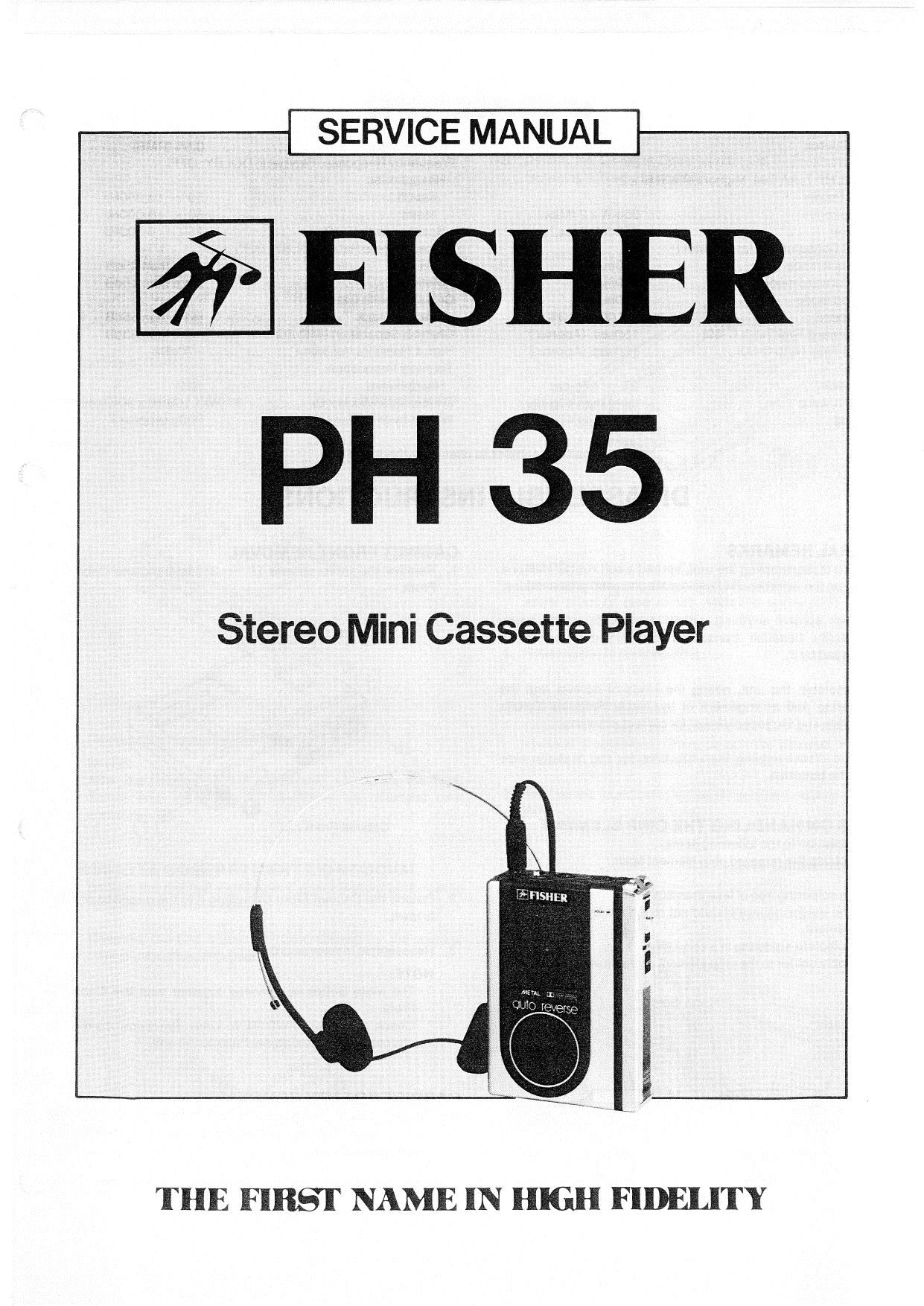
Fisher PH 35 Service Manual

This is the 19 pages manual for Fisher PH 35 Service Manual.
Read or download the pdf for free. If you want to contribute, please mail your pdfs to info@audioservicemanuals.com.

Page: 1 / 19
left right
Fisher PH 35 Service Manual

Extracted text from Fisher PH 35 Service Manual (Ocr-read)


Page 1

SERVICE MANUAL

if FISHER

PH 35

Stereo Mini Cassette Player

THE FIRST NAME IN HIGH FIDEIJTY

Page 2

SPECIFICATIONS

Power Source


DC ......................................... 3V

(UM-3, HP 7, AA Cell, Mignonzelle. R 6) x 2
Output Power

Headphones .. 25me 2 (Max)

Speaker ......... . 220mW (Max)
Current Consumption (at Vol. Min.)

Playback mode ....... . 110mA

Fast Forward mode 140mA

Rewind mode .. 140mA

Tape Speed ...... 1-7/8ips. 213%
Fast Forward Time (with 0-60) 1505ec. (Approx)
Rewind Time (with 0-60) ................. 150sec. (Approx)


Wow 8. Flutter ............................. 0.5% (RMS)
Frequency Response (Playback, DOLBY: OFF)
Headphones
F6203 . 50 ~- 14,000Hz

. 50 N 16,000HZ
250 ~ 6,300Hz

Metal
Speaker (with Fean) ...................
Signal to Noise Ratio (DOLBY' OFF)

Fe203 ..................................... more than 45dB

Metal more than 48dB
Crosstalk (with FezOs)

Track to Track ................... . more than 55dB
Channel Separation (with Fe203) . . more than 35dB
Hum& Noise (at Vol. Min.) ................ -70st
Terminal Impedance

Headphones ........................ 3212


. 81 (W) x 109(H) XSOID) mm
............. 300g (Approx)

Dimensions (W x H x D) .
Weight (with Batteries)

-Specitications subject to change without notice.-

DISASSEMBLY INSTRUCTIONS

Torque
Playback .......... . 27 ~ 479-cm
Fast Forward more than 4OQ-cm
Rewind ............ . more than AOg-cm
GENERAL REMARKS

Before disassembling the unit, spread a soft rubber mat or a
cloth on the workbench to avoid scratches and grease stains.

Do not spread anything which is likely to cause static
electricity because transistors and ICs may be easily
damaged by it.

Reassemble the unit. noting the kinds of screws and the
soldering and arrangement 01 the leads. Refer to Circuit
Diagram and Exploded Views for correct assembly.

Before disassembling the unit, take out the cassette tape
and the batteries.

NOTES ON HANDLING THE CHIP ELEMENT
Pay due caution to the following items:
1. Do not use the removed chip element again.

2, Use a soldering iron of less than 30W.
' The soldering iron should not touch the body of the chip
element.
Complete soldering in a short time.
' Apply solder to the chip element as illustrated below.

., Solder
-7 Chip Element

Solder

Chip Element ..
Solder 7.. \

PCBoard

(Incorrect) (Correct)

CABINET FRONT REMOVAL
1. Remove the three screws (1 w 8) fastening the Cabinet
Front.

Cabinet Front is

2. Detach the Cabinet Front by pulling it in the direction of the
arrows.
3. Reassemble in reverse order.
NOTE:
The Mute Button is removed together with the Cabinet
Front.
' Check that the F.FWD/REW Lever functions correctly
after attaching the Cabinet Front to the unit.
CABINET BOTTOM REMOVAL
1. Detach the Cabinet Front by lollowing its removal
instructions. Then, remove the six screws (4 N 9) fastening
the Cabinet Bottom.
2. Detach the Cabinet Bottom by lifting it in the direction of the

arrow.