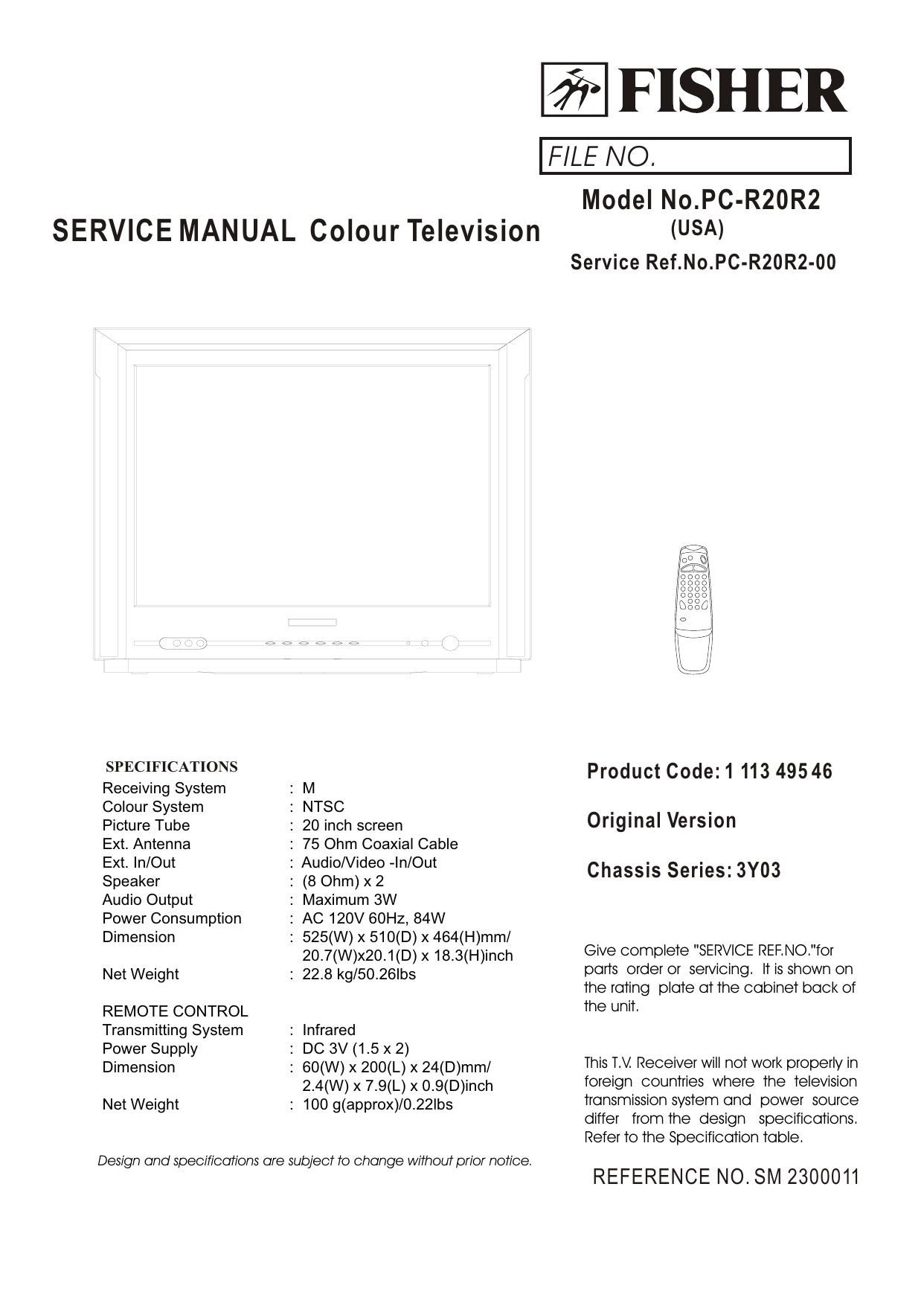
Fisher PCR 20 R 2 Service Manual

This is the 34 pages manual for Fisher PCR 20 R 2 Service Manual.
Read or download the pdf for free. If you want to contribute, please mail your pdfs to info@audioservicemanuals.com.

Page: 1 / 34
left right
Fisher PCR 20 R 2 Service Manual

Extracted text from Fisher PCR 20 R 2 Service Manual (Ocr-read)


Page 1

SERVICE MANUAL Colour Television

SPECIFICATIONS
Receiving System
Colour System
Picture Tube

Ext. Antenna

Ext. In/Out

Speaker

Audio Output
Power Consumption
Dimension

Net Weight

REMOTE CONTROL
Transmitting System
Power Supply
Dimension

Net Weight

Design and specifications are subject to change without prior notice.

: M

: NTSC

: 20 inch screen

: 75 Ohm Coaxial Cable

: Audio/Video -|n/Out

: (8 Ohm) x 2

: Maximum 3W

: AC 120V 60Hz, 84W

: 525(W) x 510(D) x 464(H)mm/

207(W)x20.1(D)x18.3(H)inch

: 228 kg/50.26|bs

: infrared
: DC 3V (1.5x2)
: 60(W) x 200(L) x 24(D)mm/

2.4(W) x 7.9(L) x O.9(D)inch

: 100 g(approx)/O.22lbs

fr FISHER

FILE NO.

Model No.PC-R20R2
(USA)

Service Ref.No.PC-R20R2-00

Product Code: 1 113 49546
Original Version

Chassis Series: 3Y03

Give complete "SERVICE REF. NO,"for
parts order or servicing. It is shown on
the rating plate at the cabinet back of
the unit.

This TV Receiver will not work properly in
foreign countries where the television
transmission system and power source
differ from the design specifications.
Refer to the Specification table.

REFERENCE NO.SM 2300011

Page 2

Contents


Safety Notice .................................................................. 2
Chassis Block Diagram... ....3
IC Block Diagram .......... ...4-7

PCB Top Layer ............ ....8-9
Service Adjustments .......................... ...10-16

Purity and ConvergenceAdjustment ........ 17
Control Location ..................................... 18
Inputand Output Terminals... ........ 19
Operation Instructions .......... .20-21
Mechanical Disassemblies ............................................. 22
Cabinet Parts List .......................................................... 23
Circuit Diagram ............................ 24
Chassis Electrical Parts List ....................................... 25-33

Safety Notice

SAFETY PRECAUTIONS

1:An isolation transformer should be connected in the power line between the receiver and
the AC line when a service is performed on the primary of the converter transformer of the
set.

2:Comply with all caution and safety-related notes provided on the cabinet back, inside the
cabinet, on the chassis or the picture tube.

3:When replacing a chassis in the cabinet, always be certain that all the protective devices
are installed properly,such as,control knobs, adjustment covers or shields, barriers,iso|a-
tion resistor-capacitor networks etc.. Before returning any television to the customer,the

service technician must be sure that it is completely safe to operate without danger of
electrical shock.

X-RADIATION PRECAUTION

The primary source of X-RADIATION in television receiver is the picture tube. The picture
tube is specially constructed to limit X-RADIATION emissions. For continued X-RADIATION
protection, the replacementtube must be the same type as the original including suffix
letter. Excessive high voltage may produce potentially hazardous X-RADIATION. To avoid
such hazards, the high voltage must be maintained within specified limit. Referto this
service manual, high voltage adjustmentfor specific high voltage limit. If high voltage exce-
eds specfied limits, take necessary corrective action. Carefully follow the instructions for

+B1 volt power supply adjustment, and high voltage check to maintain the high voltage
within the specified limits.

PRODUCT SAFETY NOTICE

Product safety should be considered whena component replacementis made in any area
of a receiver. Componentsindicated by markfi in the parts listand the schematic diagram
designate components in which safety can beof special significance. It is particularly
recommended that onlyparts designated onthe parts listin this manual be usedfor com-
ponent replacement designated bymark /!\. No deviations fromresistance wattageor vol-
tage ratings maybe made forreplacement items designated bymark i.

.2.

Page 10

Service Adjustments

Please notice the following before alignment and equipment

1. DonEt short any two soldering points, which should not be shorted and dontt touch any components,
which should not be touched.
2. Please pull out plug before equipment.
3. For safety reasons, all components equipped or replaced should be identical with BOM.
4. Must be warm up for 30 minutes or more and degauss CRT thoroughly with demagnetizer before
alignment.
The data of EEPROM must be stored before the adjustment for main chassis. And EEPROM must be
corrected by the correct file H3Y03 ROM CORRECThexH to avoid signal of CH6 weaken. R.bias,
G.bias, B.bias, R.drv, G.drv, B.drv should be set to proper values. Sub_bright is set to 63 usually.

Tools and equipments for adjustment

small H-H screwdriver
screwdriver without inductance
Pattern Generator

DC Regulated power supply
Digital Voltmeter

Sweep Signal Generator
20MHz 2-channel Oscilloscope

8979951953.

Signal condition

PICTURE SOUND
ITEMS LOGO CARRIER PA'ITERN SYSTEM MODE REMARK
1 CH14 471.25 MHz COLOR BAR NTSC/M 1'2?
BT50
2 CH3 61.25 MHz GRAY SCALE NTSC/M 0.3k,3kHz
MONO
3 CH8 181.25 MHZ MONOSCOPE NTSC/M MUSIC
4 CH12 205.25 MHz CROSS HATCH NTSC/M 4'2?

Adjust for main chassis
PIF Adjustment (45.75MHz)

a. Tuner AGC connects to GND. Pattern Generator outputs 45.75MHz l.F. signal (70db V)and connects to SAW filter
output terminal through a capacitor .

b. Connect Digital voltmeter across C227. DC Regulated power supply positive terminal output +14V to C617.

c. Adjust L203 coil to obtain 3.6V Digital voltage meter reading.

NOTE: To cancel this adjustment , L203 can be adjusted before inserted to the chassis with a special equipment.

.10.

Page 20

Operation Instructions

Turn the TV set on, then power indicator will light up. After a few seconds , the currently program number is
displayed on the top right -hand cornerofthe screen.

MENU BUTTON
1.Press this button to select menu. VIDEO, TIME, and SETUP menu can be selected cyclically.

Video Menu aAudio Menu 4» Time Menu 4» Setup Menu aEXit Menu
T (Option)

2.After enters each menu, you can select the desired adjusting item by the PROG.+I- buttons, and adjust the
item by the VOL. +/- buttons.

*When you select a item, symbols { / } will display both sides ofthe item.

Video menu
1.Enter the video menu , you can select the picture quality instantly among four

preset modes and one user-set mode.
\Mi Eggfigt l; (User-set mode)
Aedle Brlght l6 Custom 4» Standard 4» Sports 4» Movies 4» Mild
Sharpness To
Tlme Color l6
Tint 715 T
Setup
*You can adjust CONTRAST,BR|GHT , SHARPNESS , COLOR and TINT items

by pressing the VOL. +/- buttons . The adjusted level is stored in Custom mode.

Time menu

1 .CLOCK:

Video 0 k Press the VOL.- button to set hour, andthe VOL.+ button set minute.

4 OC "1"}
Audio Tlmer Ott
_ TV On 2.Tl MER

me TV 0" When you select the "Timer ON" mode, you can set the time of TVON or TV

Setup OF F.
*TV On: TheTVwill automatically turn on at the preset time.

TV Off: The TV will automatically turn off at the preset time.

.20.