Fisher MC 3015 Service Manual

This is the 13 pages manual for Fisher MC 3015 Service Manual.
Read or download the pdf for free. If you want to contribute, please mail your pdfs to info@audioservicemanuals.com.

Page: 1 / 13
left right
Fisher MC 3015 Service Manual

Extracted text from Fisher MC 3015 Service Manual (Ocr-read)


Page 1

Q/Omf _modulor III-Ii component/-
Pages 5-16 Courtesy of FISHER RADIO CORP.

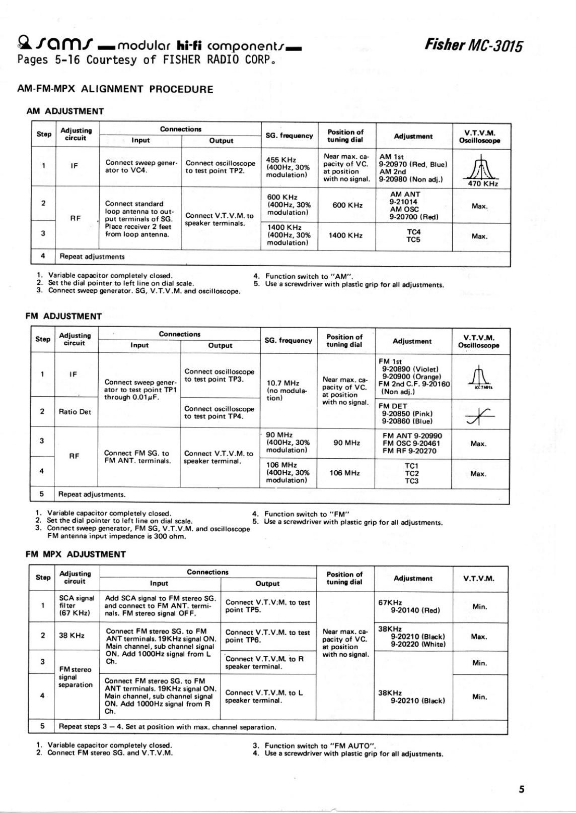
AM-FM-MPX ALlGNMENT PROCEDURE

AM ADJUSTMENT

Fisher 446-3075

Adjustin. Connection Position at V.T.V.M.
9"" circuit I... cum 36 ' tuning dill Im"m anlllolawe
Near max. ca- AM in
1 IF Connect sweep gener- Connect moilloacope zdsgowzzfiwx pacitv oi VC. 9-20910 (Red, Blue)
ator to V04, to test point TPZ. modulation) at potition AM 2nd
with no tignel. 9-20930 (Non adi.) 470 KHz
600 KHz AM ANT
2 Connect nandard (doom. 90% 600 KHz gag; Max.
n F mfijngfs 2°, gg Connect V.T.V.M. to °"°° 9-20700 (and)
Plece receiver 2 feet k" """""" 1400 KHz 1'04
3 from loop antenna. MOOHZ. 30% 1400 KHI TCE Mex
modulation)
4 Repeat adjustment:
1. Varieble capacitor completely closed. 4. Function switch to "AM".
2, Set the dial pointer to lelt line on dial male. 5. Use a ccrewdriver with plutio grip for I" ediuttrnantt.
3. Connect sweep generator. 56, V.T.V.M. and oscillotcopa.
FM ADJUSTMENT
Adlusting Cowman- Polition oi V.T.V,M.
5"" circuit In, 0mm 55' "''"V tuning iii-i I'm"m Onilloteupe
FM 1" _
1 IF Connect oscilloscope 3309069000 $362)
Com"! m _ to test point m, Near max. oa- "9
eep gener 10.7 MHz oci 0' VC FM 2nd C.F. 920180 1.
star to test point on (no module- :2 gm ' (Non adj.)
throum 0.01uF, co non) with no signal. FM DET
. nnect oscilloscope .
2 Ratio Det w m mm W 9.20350 (Pink) 71.;
9-20860 (Blue)
' 90 MHz FM ANT 9-20990
3 (400H1,.30% 90 MHz FM OSC 9-20481 Max.
RF Connect FM so. to Connect v.T.\I.M. m '"°"""°" F "F 9'20"
FM ANT. terminals. speaker terminel. 106 MHz TC1
4 sz. 30% IDS MHz TC! Mex.
modulation) TC3
5 Repeat ediustmente.
1. Vuiable capacitor completely closed. 4. Function switch to FM"
2. Set the dial pointer to left line on dial scale. 5. Use a ficrewdriver with plastic grip tor ell adjustments.
3. Connect sweep generator, FM SG, V.T.V.M. and oscilloscope
FM antenna input impedance it 300 ohm.
FM MPX ADJUSTMENT
Mlmflnu Connoctiom Position 01
Step circuit Input 0mm tuning dial Mlunment VT'V'M'
SCA xi al Md SCA sign! to FM stereo SG.
1 filter n and connect to PM ANT. termi- °°i"";'1-;g"TV'M- '° " $50140 (Rm) Min.
(67 KHz) nils. FM stereo iignl OFF. 9°
JBKHI
Connect FM Item 56. to FM Connect V.T.V.M. to ten Nut max. co-
? 3'3 "1 ANTterminoIe. isxnzsignai ON. poi." ms, pacity cl vc. Eggs $35)) M
Main chennel, sub channel tignal at position I
3 00?? Add IOOOHI signal lrom L 'Connect V.T.V.IVL to R wuth Malena. Min
FM "90 ' spuker terminal.
nglion Connect FM stereso $6. to FM
ANT terminals. 1 KHz signal ON.
4 Nhin channel, sub channel tint: mlzftznliXdM 0 L 3831.502 (Black) Min.
ONt Add 100on signal 'rom
Ch.
5 Repeat step: 3 - 0. Set at pniiliofl with max. channel separation.

1. Variable capacitor completely cloud.
2. Connect FM stereo SG. and V.T.V.M.

3. Function Mitch to "FM AUTO".

4, Ute a Icrewdrivor with plattlc grip lor ell adiustmenu