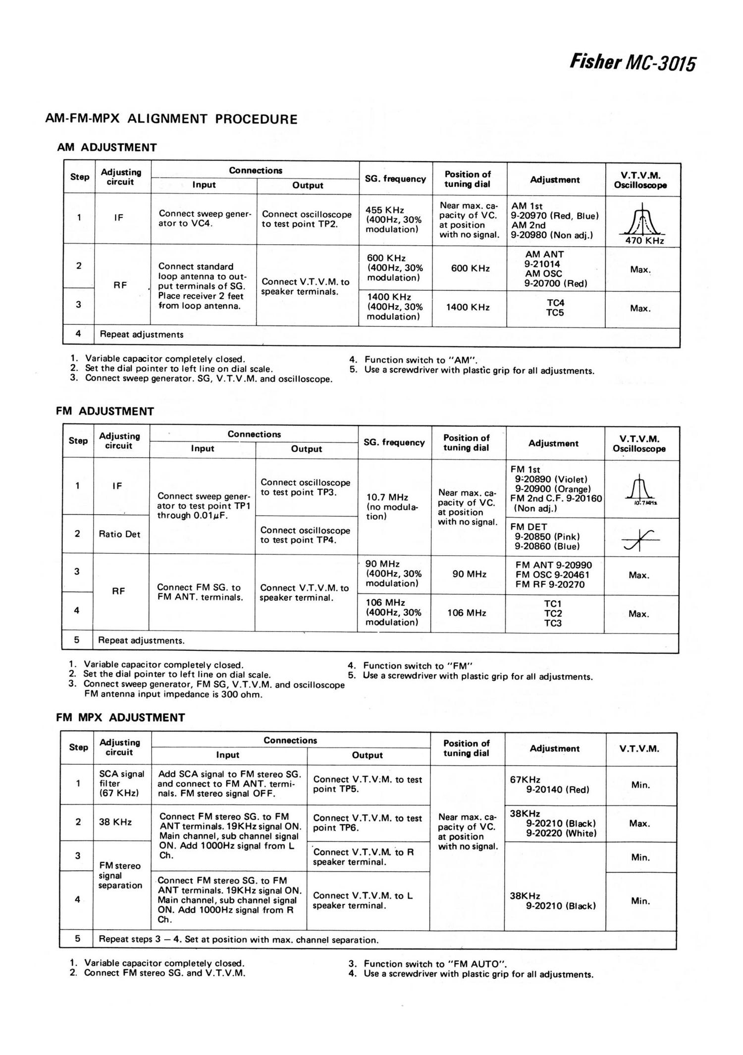
Fisher MC 3015 Schematic

This is the 10 pages manual for Fisher MC 3015 Schematic.
Read or download the pdf for free. If you want to contribute, please mail your pdfs to info@audioservicemanuals.com.

Page: 1 / 10
left right
Fisher MC 3015 Schematic

Extracted text from Fisher MC 3015 Schematic (Ocr-read)


Page 1

AM-FM-MPX ALIGNMENT PROCEDURE

AM ADJUSTMENT

Fisller MC «5'07 5

L _ ._____r . t 1
Adjusting Connoctions Position of . V.T.V.M.
' Step circuit INPUt Output 56. frequency tuning dial Adjustment Oscilloscope
455 KHz Near max. ca- AM 1st
1 IF Connect sweep gener- Connect oscilloscope (400Hz 30% pacity of VC. 9-20970 (Red, Blue)
ator to VC4. to test point TP2. '. at position AM 2nd
modulation) with no si nal 9-20980 (Non ad' )
I 9 ' - 470 KHz
2 Connect standard (400Hz, 30% 600 KHz AM OSC Max
I _ .
R F pouiptgpmfirqgl: Lof :3 Connect V.T._V.M. to modulation) 9-20700 (Red)
Place receiver 2 feet speaker terminals. 1400 KHz TC4
3 from loop antenna. (400Hz, 30% 1400 KHz T05 Max.
modulation)
4 Re eat ad'ustments
r4 r p l

1. Variable capacitor completely closed.
2. Set the dial pointer to left line on dial scale.
3. Connect sweep generator. 86, V.T.V.M. and oscilloscope.

FM ADJUSTMENT

4. Function switch to "AM".
5. Use a screwdriver with plastic grip for all adjustments.

:- - r ---- __ - t i
Adjusting Connections Position of . V.T.V.M.
Step circuit Input Output 56' frequency tuning dial Adjustment Oscilloscope
r FM 1st
1 IF Connect oscilloscope 338338 96'0"),
Connect swee to test point TP3. Near max. ca- ' range
p gener- 10.7 MHz acit of VC FM 2nd C.F. 9-20160 ,Mm
ator to test point TP1 (no modula- p y- . ' (Non adj.)
j through 0.01uF. tion) fiifh°zgggnal
. ' FM DET
2 Ratio Det fo°gegi°gofif§+$f°pe 9-20850 (Pink) %
' 9-20860 (Blue)
' 90 MHz FM ANT 9-20990
3 (400Hz,.30% 90 MHz FM OSC 9-20461 Max.
RF Connect FM SC. to Connect V.T.V.M. to modulation) FM RF 940270
I FM ANT. terminals. speaker terminal. 106 MHz TC1
4 (400Hz, 30% 106 MHz TC2 Max.
modulation) TC3
5 Repeat adjustments.
1. Variable capacitor completely closed. 4. Function switch to FM"
2. Set the dial pointer to left line on dial scale. 5. Use a screwdriver with plastic grip for all adjustments.
3. Connect sweep generator, FM 56, V.T.V.M. and oscilloscope
FM antenna input impedance is 300 ohm.
FM MPX ADJUSTMENT
a r - - . .7 - T
' MiUStino Connections Position of . .
Step circuit Input Output tuning dial Adjustment V.T.V.M.
i
SCA signal Add SCA signal to FM stereo SG. _
1 filter and connect to FM ANT. termi- ngsefgg/I'V'M' to test 67.330140 (Red) Min.
(67 KHz) nals. FM stereo signal OFF. p '
Hz
Connect FM stereo $6. to FM Connect V.T.V.M. to test Near max. ca- 38K
38 KHZ ANT terminals. 19KHz signal ON. point TP6_ pacity of VC. 3-33318 :lgllgctk) Max.
Main channel, sub channel signal at position ' e
. . . . . l.
(ODIN. Add 1000Hz Signal from L Connect V.T.V.M. to R With no signa Min
FM stereo ' speaker terminal. '
signal Connect FM stereo $6 to FM
separation ANT terminals. 19KHz.signal ON.
Main channel, sub channel signal Connect V'T'VM' to L 38KHZ Min.

ON. Add 1000Hz signal from R
Ch.

speaker terminal.

9-20210 (Black)

5

11+

Repeat steps 3 - 4. Set at position with max. channel separation.

1. Variable capacitor completely closed.
2. Connect FM stereo SG. and V.T.V.M.

3. Function switch to "FM AUTO".
4. Use a screwdriver with plastic grip for all adjustments.