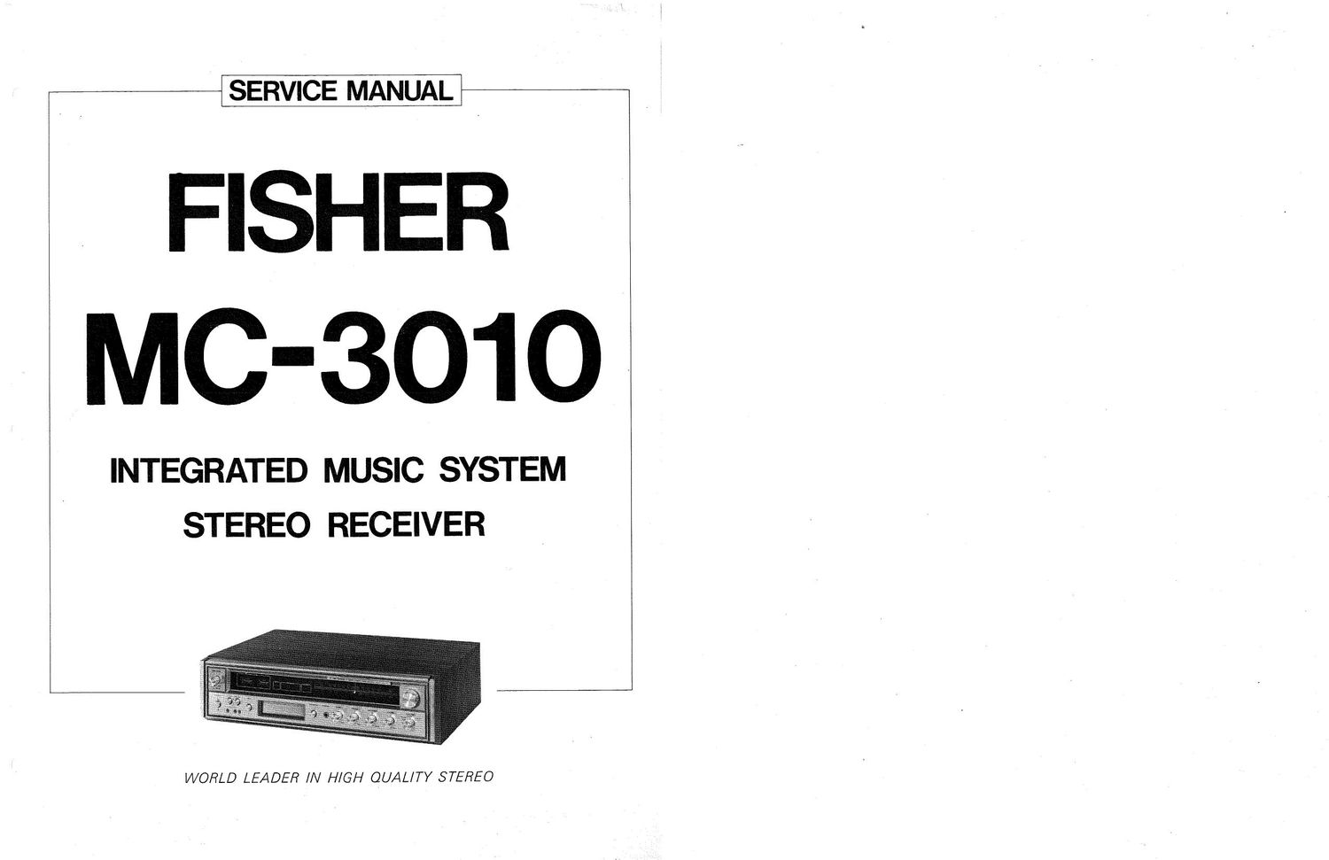
Fisher MC 3010 Service Manual

This is the 20 pages manual for Fisher MC 3010 Service Manual.
Read or download the pdf for free. If you want to contribute, please mail your pdfs to info@audioservicemanuals.com.

Page: 1 / 20
left right
Fisher MC 3010 Service Manual

Extracted text from Fisher MC 3010 Service Manual (Ocr-read)


Page 1

SERVICE MANUAL

FISHER
MC-3010 ~

INTEGRATED MUSIC SYSTEM
STEREO RECEIVER

WORLD LEADER IN HIGH QUALITY STEREO

Page 2

i

1
l

SPECIFICATIONS

FM TUNER SECTION

Usable Sensitivity (IHF Standard)

SuV

Harmonic Distortion (at 400 Hz, 100% Modulation)

Mono 1.0%
Stereo 15%

Signal-to-Noise Ratio (at 100% Modulation &

1mV Input) GOdB
Selectivity 35dB
Image Frequency Rejection (at 88 MHz) 40dB
IF Frequency Rejection (at 88 MHz) 70dB
FM Stereo Separation (at 1 KHz) SOdB
Capture Ratio, IHF, at 1mV 3:18
AM TUNER SECTION
Usable Sensitivity (lHF Standard) S/N 20dB

Loop Antenna 250uV/m
Selectivity (at 1 MHz & :10 KHz) 30dB
Image Frequency Rejection (at1 MHZ) SOdB
IF Frequency Rejection (at 1 MHz) 40dB
AMPLIFIER SECTION
Total Continuous (RMS) Power (at 8 ohms) 10W (5 + 5W)
Harmonic Distortion (at 60 Hz to 15 KHz,

Rated Power) 1.0%
Power Bandwidth, (IHF Standard) 40 7 15,000 Hz

Sensitivities (for rated output power at 8 ohms,

l KHz)/lmpedances

DIAL CORD STRINGING

8 TRACK TAPE DECK ADJUSTMENT

2.5mV/50K ohm
300mV/1M ohm
200mV/100K ohm
1,0mV/600 ohm

Phono (Magnetic)
Phono (Ceramic)
Auxiliary
Microphone

Hum & Noise (below rated output)

Phono (Magnetic) 62dB

Phono (Ceramic) 62dB

Auxiliary 62dB
Frequency Response i2.0dB 40 - I5,000 Hz
Bass Control Range (at 100 Hz) :SdB
Treble Control Range (at 10 KHz) t8dB

Loudness Control (at 40dB volume attenuation

fixed)

+8dB at 100 Hz
+5dB at 10 KHz

TAPE SECTION

Tape Speed (Play 81 Record) 3.75 ips
(Fast Forward) 3,75 ips x 2
Wow and Flutter, maximum 0.2%
Signal-to-Noise Ratio (Play & Record) 40:33
Channel Separation 35dB
Crosstalk 45dB
Distortion 2.0%
Erasure Ratio 55dB
Recording Sensitivity
Microphone 1mV
Auxilian/ 200mV
G ENERAL
AC Power 120V
Frequency 50/60 Hz
Consumption 70 Watts
Dimensions (including control panel, cabinet) 2143/32" W
63/32" H
13-21/32 D

puthv

1. Recommended Test Equipment

at
b.

Two Vacuum Tube Volt Meters
Test tapes RCA-321, Pony-806, or Victor-801
(Track 1 and 3 with 1kHz and track 6 with 8kHz test signals)

2. Head Height Adjustment

a.
b.

c.

d.

Use test cartridge tape (RCA-321 or Pony-806).

Push program selector button to position tapehead to track 2
(on channel 2).

Connect two Vacuum Tube Volt Meters to left and right
channels.

Turn the head height adjust screw slowly counterclockwise or
clockwise and adjust for a null. For correct tapehead position,
make sure there is a peak on either side of the null at the point
where the output is minimum. Glyptol screw after correct
positioning is attained.

e.

Switch to channel 4 and back to 2 again, make sure that the
output on channel 2 is at minimum. Should the output on
channel 2 be greater than on channel 4, repeat adiustments.

Azimuth Adiustment

a.

Use test tape cartridge RCA-321.

b. Set tape player to track 2.

Connect two Vacuum Tube Volt Meters to the left and right
output channels.

Adiust screw (A) with Phillips screwdriver for a balance at
maximum output.

. Glyptol adjust screw after correct positioning is attained.