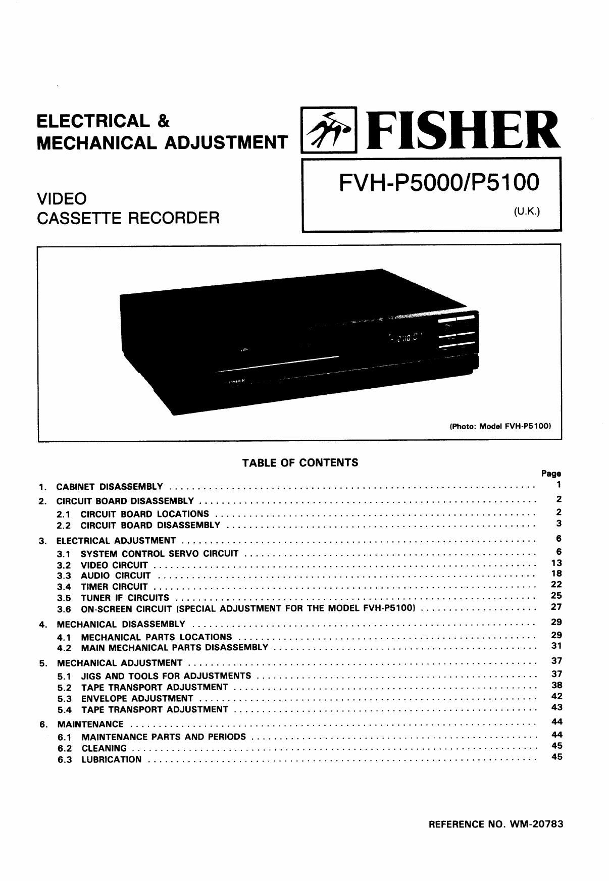
Fisher FVHP 5100 Service Manual

This is the 57 pages manual for Fisher FVHP 5100 Service Manual.
Read or download the pdf for free. If you want to contribute, please mail your pdfs to info@audioservicemanuals.com.

Page: 1 / 57
left right
Fisher FVHP 5100 Service Manual

Extracted text from Fisher FVHP 5100 Service Manual (Ocr-read)


Page 1

ELE°T'°A FISHER
MECHANICAL ADJUSTMENT

CASSEI IE RECORDER (U'K')
(Photo: Model FVH-PSIOOI
TABLE OF CONTENTS

Page
1. CABINET DISASSEMBLY ................................................................ 1
2. CIRCUIT BOARD DISASSEMBLV .......................................................... 2
2.1 CIRCUIT BOARD LOCATIONS ....................... 2
2.2 CIRCUIT BOARD DISASSEMBLY ............................ . . . . ............... 3
3. ELECTRICAL ADJUSTMENT ......................................................... 6
3.1 SYSTEM CONTROL SERVO CIRCUIT ........ 6
3.2 VIDEO CIRCUIT ................................... 13
3.3 AUDIO CIRCUIT .. 18
3.4 TIMER CIRCUIT ..... 22
3.5 TUNER IF CIRCUITS ........................................................ 25
3.6 ON-SCREEN CIRCUIT (SPECIAL ADJUSTMENT FOR THE MODEL FVH-PSIOOI ..................... 27
4. MECHANICAL DISASSEMBLY ............................................................. 29
4.1 MECHANICAL PARTS LOCATIONS ................................................. . . . 29
4.2 MAIN MECHANICAL PARTS DISASSEMBLY .......................................... 31
5. MECHANICAL ADJUSTMENT ........................................................ 37
5.1 JIGS AND TOOLS FOR ADJUSTMENTS ............... . . . . . 37
5.2 TAPE TRANSPORT ADJUSTMENT ...................................................... 38
5.3 ENVELOPE ADJUSTMENT ........ 42
5.4 TAPE TRANSPORT ADJUSTMENT .............................................. 43
6. MAINTENANCE ................................................ , . . 44
6.1 MAINTENANCE PARTS AND PERIODS . . . . 44
6.2 CLEANING ................................................................ . . . , . 45
6.3 LUBRICATION ..................................................................... 45

REFERENCE NO. WM~20783

Page 2

1. CABINET DISASSEMBLY

Note: Do not push or pull the clamps strongly, as damage

When disassembling the following parts, remove the screws

may OCCUI.

shown in the figure in numerical order, and remove the parts
in the direction of the arrows while pulling the clamps.

Top Cover

Cabinet, From

Bottom Cover

Page 10

3.1.4 ADJUSTMENTS

0 For test equipment connecting diagrams for adjust-
ments (1) through (4) in this section, refer to the cor-
responding diagrams (number in parentheses) in Section
3.1.3.

Note:
ADJ. is the abbreviation for adjustment in following section.

(1) CH1 PHASE/CH2 PHASE (PLAY MODE)

WWW

Video Si ma)
9 Vertical sync signal

leading edge

SW PULSE
Fall

Tl=6.5H:O.5H

Fig. 3.1.9

3. Adjust VR702 (CH2 PHASE) so that the width "T2
becomes 6.5 H 1' 0.5 H as shown in Fig. 3.1.10.

Measuring Point Measuring Equlpmam ADJ. Condition
Pin 1 of TP2 Oscilloscope PLAY mode
(P8204) Test Tape
(PB FM) (VPM-6)
(on Head Amp
PC Assy)
Pin 1 of TP701
(SW PULSE)
Pin 4 of TP701
(GND)
VIDEO OUTPUT
terminal

ADJ. Location ADJ. Value
VR151 Maximum level
(TRACKING control knob) (PB FM Signal)
VR701 (CH1 PHASE) 6.5 H 1 0.5 H
VR702 (CH2 PHASE) 6.5 H 1 0.5 H

1. Adjust VR151 (TRACKING control knob) behind the
door on the front panel so that the PB FM Signals for
both CH1 and CH2 are brought to their maximum lev-
els. (Refer to Fig. 3.1.8)

. .
Maximum PB FM Signal
level

. .

CH2 CH2 CH2

_ ,-

sw PULSE
CH1 CH1
Fig. 3.1.3

T2
1 H 0.5 H
. . /'
Video Signal Vertical sync signal
leading edge
' SW PULSE
Rise
T2 = 6.5H 2 0.5H
Fig. 3.1.10

2. Adjust VR701 (CH1 PHASE) so that the width "T1"
becomes 6.5 H t 0.5 H as shown in Fig. 3.1.9

(2) PLAY MODE TRACKING

Refer to Section 5.2.4 (AUDIO CONTROL ERASE HEAD)
before making these adjustments.

Measuring Point Measuring Equlpmem ADJ. Condltion
Pin 1 of TP701 Oscilloscope PLAY mode
(SW PLUSE) Test tape
Pin 2 of TP701 (VPM-6)
(CTL PULSE)
Pin 4 of TP701
(GND)

ADJ. Location ADJ. Value
VR703 (NORMAL TRACK) 410 usec 1- 200 usec

Page 22

3. Adjust the azimuth adjustment screw so that the AC
voltmeter's reading is brought to its maximum level.
(Refer to Fig. 3.3.8)

Azimuth Adjustment Screw
Fig. 3.3.8

4. If the AC voltmeter's reading in step 2 increased more
than 2 dB after step 3, perform step 2 again.

Note: The maximum reading on the AC volmeter obtained
in steps 2 and 3 is approxmateiy - 10 dBV.

(2) ACE HEAD AZIMUTH

Refer to Section 5.2.4 (AUDIO CONTROL ERASE HEAD)
before making these adjustments.

Measuring Point Measuring Equipment ADJ. Condition
VIDEO OUTPUT Oscilloscope PLAY mode
terminal AC voltmeter Test tape
(VPM-6)
ADJ. Location ADJ. Value

Azimuth adjustment screw Maximum level
(AC voltmeter)

1. After confirming on the oscilloscope that a 1 kHz sine
wave is being output, adjust VR401 (PB LEVEL ADJ.)
so that the AC voltmeters reading is - 10 dBV : 1 dB.

(4) BIAS LEVEL
[A]

Measuring Point Measuring Equipment ADJ. Condition
TP402

Colour bar generator REC mode

TP401 (GND) Oscilloscope Blank tape
AC voltmeter
ADJ. Location ADJ. Value

VR402 (BIAS LEVEL ADJ.) 16 mVrms 1 2 mVrms

Notes: 0 Connect the colour bar generator to AUDIO IN-
PUT terminal. (Refer to Fig. 3.3.4)
0 Insert the dummy plug in to the AUDIO INPUT

terminal. (Refer to Fig. 3.3.4)

1. After confirming on the oscilloscope that a 70 kHz sine
wave is being output, adjust VR402 (BIAS LEVEL ADJ.)
so that the AC voltmeters reading is 16 rnVrms
i 2 mVrms.

[BI

1. After confirming on the oscilloscope that a 6 kHz sine
wave is being output, adjust the azimuth adjustment
screw so that the AC voltmeters reading or oscillo-
scope waveform is brought to its maximum level. (Refer
to Fig. 3.3.8)

Note: The maximum reading on the AC voltmeter obtained
in step 1 should be be more than - 5 dB below the
value given in Section 3.3.4 (1).

(3) PLAY MODE LEVEL

Measuring Point Measuring Equipment ADJ. Condition
VIDEO OUTPUT Oscilloscope PLAY mode
terminal AC voltmeter Test tape
(VPC-1)
ADJ. Location ADJ. Value

VR401 (PB LEVEL ADJ.) - 10 dBV : 1 dB

Measuring Polnt Measuring Equipment ADJ. Condition
AUDIO OUTPUT Oscilloscope

Self-recording

terminal AC voltmeter Blank tape
Standard audio signal
generator (86)
Colour bar generator
ADJ. Location ADJ. Value

VR402 (BIAS LEVEL ADJ.) -2 dB ~ +2 dB
between 1 kHz and 10 kHz

Notes: 0 Connect the colour bar generator to AUDIO IN-
PUT terminal.
0 Connect the standard audio signal generator to

AUDIO INPUT terminal. (Refer to Fig. 3.3.5)

1. Set the standard audio signal generators frequency to
1 kHz and then 10 kHz. Record each frequencys
signals.

2. Playback the just-recorded portion.

3. Confirm that the difference between AC voltmeters
readings for the 1 kHz and 10 kHz signals is between
-2 dB ~ +2 dB.

4. If the difference is under - 2 dB, rotate VR402 (BIAS
LEVEL ADJ.) slightly clockwise (seeing from the foil
side) to adjust it.

5. If the difference is over +2 dB, rotate VR402 (BIAS
LEVEL ADJ.) slightly counterclockwise (seeing from the
foil side) to adjust it.

6. Repeat steps 1 through 5, if necessary.

__21_

Page 35

4.2.9 LINK LOAD T COMPLETE] LINK LOAD'S COMPLETE 4.2.11 UPPER CYLINDER

® @ Prior to removing the upper cylinder, remove the soldered
3 9 connection of the four lead wires inside the upper cysinder

Link Complete,
Loading Supply

Link Complete, (2
Loading Take-Up z
i 1 u

Select Switch

(«(19 ®
«a; (-3

Gear Assy,
Sector

/ Plate Assy,
Grounding

/ Cylinder Upper

Fig. 4.2.14

4.2.10 CYLINDER

Cylinder Complete


Motor, Cylinder F 4 2 16
lg. . .

Notes:

a) As the cylinder is a precision part, take care not to
damage the heads or the tape transport area.

bl Hold the side of the upper cylinder (the tape transport
area), and pull it upwards while turning it gradually to
avoid excessive force. If the upper cylinder does not
come off, it should be heated with a dryer to about
40°C before removal.

0) When installing the cylinder, tighten two screws ®
uniformly to obtain a 5 kg-cm to 6 kg-cm torque value.

d) Prior to reassembiing, clean up the contact surface on
the upper cylinder with cleaning fluid. (Refer to Fig.
4.2.16)

e) After reassembiing the cylinder, clean up the tape trans-

port area with cleaning fluid and Chamois. (Refer to Fig.
Flo. 4.2.15 4.2.16)

-34_