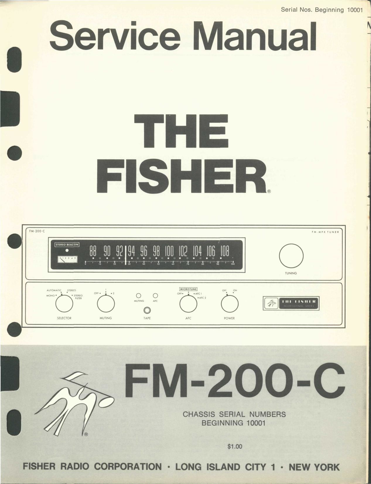
Fisher FM 200 C Service Manual

This is the 10 pages manual for Fisher FM 200 C Service Manual.
Read or download the pdf for free. If you want to contribute, please mail your pdfs to info@audioservicemanuals.com.

Page: 1 / 10
left right
Fisher FM 200 C Service Manual

Extracted text from Fisher FM 200 C Service Manual (Ocr-read)


Page 1

Serial Nos. Beginning 10001

Service Manual

2141

I

I
' THE 7

FISHER l

MMMMMMMM

NNNNNN

CHASSIS SERIAL NUMBERS
BEGINNING 10001

®
$1.00

FISHER RADIO CORPORATION - LONG ISLAND CITY 1 - NEW YORK

Page 2

CAUTION: This is a FISHER precision high-fidelity in-
strument. It should be serviced only by qualified personnel -
trained in the repair of transistor equipment and printed circuitry.

EQUIPMENT AND TOOLS NEEDED

The following are needed to completely test and align modern high-fidelity instruments
such as amplifiers. tuners and receivers.

Test Instruments

Vacuum-Tube Voltohmmeter DC VTVM

Audio (AC) Vacuum-Tube Voltmeter (AC VTVM]
Oscilloscope (Flat to 100 kc minimum)

Audio (Sinewave) Generator

lntermodulation Analyzer

Sweep (FM) Generator (88 to 108 me)

Marker Generator

Multiplex Generator (preferably with RF output-

FISHER Model 300 or equal).

Miscellaneous

AdjustableLine-Voltage Transformer or
line~voltage regulator

Load Resistors (2)-8-ohm, Sorwatt (or higher)

Stereo source (Turntable with stereo cartridge
or Tape Deck)

Speakers (2) Full-range, for listening tests

Soldering iron (with small-diameter tip).
Fully insulated from power line.

- PRECAUTIONS -

Many of the items below are included just as a re-
minder-they are normal procedures for experienced
technicians. Shortcuts can be taken but often they
cause additional damage-to transistors, circuit com»
ponents or the printed-circuit board.

Soldering-A well-tinned, hot, clean soldering iron tip
will make it easier to solder without damage to the
printed-circuit board or the many many circuit com-
ponents mounted on it. It is not the wattage of the
iron that counts-it is the heat available at the tip.
Low»wattage soldering irons will often take too long to
heat a connection-pigtail leads will get too hot and
damage the part. Too much heat, applied too long, will
damage the printed-circuit board. Some 50-watt irons
reach temperatures of 1,000°F-others will hardly
melt solder. Small-diameter tips should be used for
single solder connections-larger pyramid and chisel
tips are needed for larger areas.

o When removing defective resistors, capacitors, etc.,
the leads should be cut as close to the body of the
circuit component as possible. (If the part is not being
returned for invwarranty factory replacement it may be
cut in half-with diagonal-cutting pliers-to make
removal easier.)

u Special de~soldering tiplets are made for unsolder-
ing multiple-terminal units like lF transformers and
electrolytic capacitors. By unsoldering all terminals at
the same time the part can be removed with little
chance of breaking the printed~circuit board.

u Always disconnect the chassis from the power line
when soldering. Turning the power switch OFF is not
enough. Power-line leakage paths, through the heating
element, can destroy transistors.

Transistors~Never attempt to do any work on the
transistor amplifiers without first disconnecting the
AC-power linecord-wait until the power supply filter-
capacitors have discharged.

- Guard against shorts-it takes only an instant for
a base-to-collector short to destroy that transistor and
possibly others direct-coupled to it. [In the time it
takes for a dropped machine screw, washer or even
the screwdriver, to glance off a pair of socket terminals
(or between a terminal and the chassis) a transistor
can be ruined]

0 DO NOT bias the base of any transistor to, or near,
the same voltage applied to its collector.

- DO NOT use an ohmmeter for testing transistors.
The voltage applied through the test probes may be
thighelrtthan the base-emitter breakdown voltage of the
ransrs or.

Output Stage and Driver-Replacements for output
and driver transistors, if necessary, must be made from
the same beta group as the original type. The beta
group is indicated by a colored dot on the mounting
flangepf the transistor. Be sure to include this in-
formation, when ordering replacement transistors.

o If one output transistor burns out (open or shorts),
always remove all output transistors in that channel
and check the bias adjustment, the control and other
parts in the network with an ohmmeter before insert-
ing a new transistor. All output transistors in one
channel will be destroyed if the base-biasing circuit
is open on the emitter end.

a When mounting aireplacement power transistor be
sure the bottom of the flange, the mica insulator and
the surface of the heat sink are free of foreign matter.
Dust and grit can prevent perfect contact. This re-
duces heat transfer to the heat sink. Metallic particles
can puncture the insulator and cause shorts-ruining
the transistor.

- Silicone grease must be used between the transist-
or and the mica insulator and between the mica and
the heat sink for best heat conduction. Heat is the
greatest enemy of electronic equipment. it can shorten
the life of transistors, capacitors and resistors. (Use
Dow-Corning DC-3 or C20194 or equivalent compounds
made for power transistor heat conduction.)

. Use care when making connections to speakers and
output terminals. Any frayed Wire ends can cause
shorts that may burn out the output transistors-they
are direct-coupled to the speakers. There is no output
transformer - nothing to limit current through the tran-
sistors except the fuses. To reduce the possibility of
shorts at the speakers, lugs should be used on the
exposed ends-at least the ends of the stranded wires
should be tinned to prevent frayed wire ends. The
current in the speakers and output circuitry is qwte
high. Any poor contact or small-size wire, can cause
power losses in the speaker system. Use, or 16 AWG
for long runs of speaker-connecting wiring.

DC-Voitage Measurements-These basic tests of the
transistor circuitry are made without the signal gener-
ator. Without any signal input measure the circmt volt-
ages-as indicated on the schematic. The voltage
difference between the base and the emitter should
be in the millivolt range-a sensitive DC meter is
needed for these readings. A low-voltage range of lvolt,
full scale~-or loweriis needed.

Audio-Voltage (gain) Measurements-The schematic
and printed-circuit board layout diagrams are used.
Input signals are injected at the proper points-found
most quickly by using layout of the printed-circuit
board instead of the schematic. An AUDIO (AC) VTVM
connected to the test points should indicate voltages
close to those values shown in the boxes on the sche-
matic. Many of the signal levels in the input stages
are only a few millivoltsethey can not be read on the
AC ranges supplied on most Vacuum-Tube AC/DC Volt-
ohmmeters (VTVMs). Even with a l-volt range a signal
level of 100 millivolts (.lvolt) will be the first 1/10
of the meter scale. A reading of 1 millivolt (.001 volt)
will hardly even move the meter needle.

Page 5

I249 MULTIPLEX DECODER


WIth whlch It WIII be used. Check the allgnment of the
IF stages before making multiplex adjustments. Poor IF
alignment can make proper muItIplex operatlon Im-
possrble.

Thls table is based on the FISHER Model 300 multl-
plex generator. Another allgnment procedure, for MPX
generators wtthout an RF output, IS shown In Table 2. I

TO
STEREO-MONO
SWITCH
4L

MULTIPLEX DECODER TESTS '- -cqo1 - - _ - _ - - _ _ _ an" _____ "" 04m (3402 9403

| 4UP PgoL _ _ _ coon .OIUF | 2N2924 2N25I4 2N26|4
.Modulate FM generator With )9 to, -o 5 kc dovro. | H I}... .. .3 4,00 ,_| |__.
tlon (Use external rnoaulotron rt necessflry.) '- -c-R- - I }_. Ist I c

402
0 Connect tno FM gonarotot output to the antenna I ,i 3- I B
I t It ._._ _ ._ a- W ._ - O-wv-4
termlnd s o t e umtundet test I r O 12 g 2 [- ,U. _I ;* "1 ml I +0.58V E +20 4V E
owrtlt tlto FM generator set tor on output at 25 uv at 0 a: 3402 o O 5 o-Jwv-o - S
the antenna terminals tno storoo lndlcator should lrgnt Ivo In «(I 02 I f I "03 3 In or «JR 3 II
up It too generator output ls reduced to 5 av, at tho I32 3 3 3 5°, I ; * 3* E T 04°
antenna tornnnols, the lndlcator It nt should Iemaln 0N 0' 0 -I . I v: I" m I T""5 0405 0406
9 z 5 0RTl-AIT 2N2924 2N2524
- Reduce FM gonorotor output to zero and the Indlcator l l. | H 0. I . | ,5 L403 I - c c c
Irgltt snould go OFF I 0. call I 8 C 20MH
.0l5 ~ o-I I-«o

III the ste)eo lndlcotor lrgtrt does not respond properly 5+ L- - '0' -' -13 "' 4'0 L - "I - 1 c4112: I E B 3
to the tests above, teudlost the trrggor control (RAol) I 5 53° HRH | E E E
untlI the stereo Indlcatur Iatnp .ust turns ON wrtn a . 2-1-1 .ol g-ongmU-r'r ** **
4 uv stanal opplrod to the antenna termlnuls | _x .cn 03 .I 0-) I-. I4

-so 5° it E c420

|9° z- '* cl ©4fi

I, .
PREFERRED I'm 1. 5 .I " ._I |_.. I = K
e c
ALIGNMENT INSTRUCTIONS I L3 4-! 4th (9-4H 12:? m mm m
(Using multiplex generator with RF and I9 kl: TRIGGER © . 94 O-IG-O I GENERATOR
outputs and with I In: modulation) A69 48 .50
In Table 1, below, a multlplex generator wvth an RF I

output ls used. Thls IS the better method of allgnment I 5
smce the multlplex Clrcultry IS connected to the tuner I g T (N5 28)

I

tIGURE I. Multiplex-alignmem pass litter (HUII.

ALTERNATE ALIGNMENT INSTRUCTIONS

INSZBBA [For multiplex generators without an RF output)
TEST EQUIPMENT: Multlplex Generator, Audlo

(AC) Vacuum-Tube Voltmeter (RMS type preferred).
Vacuum-Tube VoltohmeterlDC VTVM),OscH|oscope (100
kc mlnlmum) with external sweep Input.

Disconnect the ratio detector from the multlplex unlt
before usIng thls procedure. A low-pass filter (Figure I)
Is used between the MPX generator output and the in-
put to the multiplex clrcultry. It has about the same

WARNING: Use only the proper alignment tool to * FOR VALUE REFER TO STEREO 402 40' ** VOLTAGE FOR 249" I5 +°~5V loading effect as the output of the ratlo detector in the
prevent core breakage. PARTS LIST BEACON PlZ49-2 IS +0.35V tuner.
COMPOSITE OUTPUT 0F MULTIPLEX GENERATOR CONNECTED TO INPUT OF MPX DECODER THROUGH LOW-PASS FILTER
MULTIPLEX'GENERATOR RF OUTPUT CONNECTED TO ANTENNA TERMINALS
" ' K ' " GENERATOR LEVEL INDICATOR TYPE AND A L I G N M E N T
GENERATOR INDICATORTYFEAND ALIGNMENT STEP
STEP RF DEV MODULATION (RMS) CONNECTION ADJUST INDICATION
MODULATION CONNECTION ADJUST INDICATION
_ 70 to 76 kc, Audto (AC) VTVM tnput Read mlnlmum AC voltage
70 to 76 kc (connect external Audra (AC) VTVM Input to Read mlnlmum AC voltage 1 100 V to TP402 with n It) pF between 70 and 76 kc
I audto generator to SCA Input * zsto TPAOZ Wlth a lo pF co- a- between 70 and 76 kc, ' copuCItor Irt ssrtos wrtlt T
at multiplex generator.) pacltot .n series wrth load, load.
2 l9 ltc pilot only .6 5 DC VTVM to TPAOI 2401, 402, 403 Maxlmum AC voltage 2 I9 )1: ptlot only 50 v DC VTVM to TPAOI 2401, 402, 403 Maximum AC voltage
, and 404 (3a Ito) ' and 404 (38 kc)
Compostta MPX Slgnui Audlo (AC) VTVM and MOxtmum AC voltage wlth Composite MPX signal Audio (AC) VTVM and Maximum AC voltage thn
It: on lett channel only a oscllioscope vertIthI tnput aloan I Ito srno wave on I )(c on left Channel onIv Osctlloscope vertlcol lnput clean I Ire stno wave on
3 *75 to lott cnonnol output Iug 02 osctlluscope 3 . 300' to lolt channel output lug Z402 osctlloscope
(AH) (4H)
Compastto MPX Stgnul Same as Step 3 MPX Separu- Mrnrmum reudmg an Audio Composrta MPX stgnal Same as Stop 3 MM Sepflrfl- Minlmum feeding on Audio
4 It: on right channel only u75k tron Control (AC) VTVMrrshouId be 4 I kc on right channel only 300 v tron Control (AC) VTVMa_sItouId be
" C IRAZI) at least 35:: below raadtng " at loost 35db below reodtng
obtatnoa tn Stop 3. obtalned tn Stop 3.
Same as Stop 4 Audio (AC) VTVM and Some Audto (AC) VTVM Same as step 4 Audra (AC) VTVM and Santa Audio (AC) VTVM
5 +75k oscilloscope vertical Input reading as obtained to 5 300 v psclIIascupa vortroal Input readtng as obtained in stop
* ° to rrgnt anannol output log T stop 3(12db),aloan Ik: to right channel output Iug \ 3 (1 Nb), alson lkc slne
(4K) sine wave on scope. wave on scope.
Same as Stop 4 Same as Stop 5 Mrnimum readlng on Audlo Same as Stop 4 Same as Step 5 Mintmum roadrng on Audto
6 75 (AC) VTVM should be at 6 300 v (AC) VTVM should be at
' least Esdb below reading m ' T least 35db below rendmg
Step 5, abtorned tn Step 5.