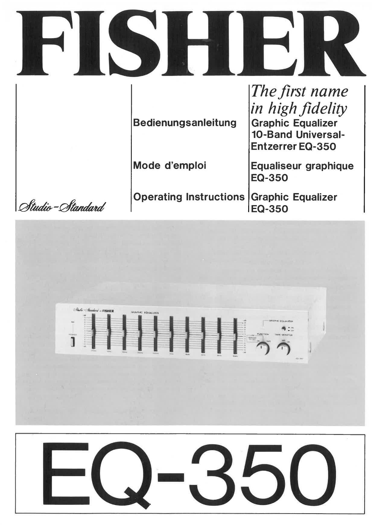
Fisher EQ 350 Owners Manual

This is the 19 pages manual for Fisher EQ 350 Owners Manual.
Read or download the pdf for free. If you want to contribute, please mail your pdfs to info@audioservicemanuals.com.

Page: 1 / 19
left right
Fisher EQ 350 Owners Manual

Extracted text from Fisher EQ 350 Owners Manual (Ocr-read)


Page 2

- lnhaltsverzeichnis -

-ZurBeachtung......... .................. 1
-TechnischeBeschreibung. 2-5
- Bedienungselemente an der Frontplatte . . . . 6 - 7
- Anschliisse an der Riickseite ................ 7
- Anschluls- und Betriebshinweise ............. 8
- Technische Daten ........ . . . ............. 9
- Hinweise zur Stiirungssuche ......... . . . . . . . 9
- Table des matiéres -
- lnformations générales . . . . . .............. 10
- Description technique. ..... . . . . ...... 10 - 11
- Commandes du panneau avant . . ....... 11 - 12

- Connexions sur le panneau arriére. . . . . . . 12 - 13
-- Information: sur les

connexions et l'exploitation ............. 13
- Fiche technique. . . . . .. .................. 14
- Guide de dépistage des pannes. . . . . ......... 14

- Table of Contents -

- General Information ..................... 15
- Technical Description . . .............. 15 - 16
- Controls on the Front Panel . . ......... 16 -- 17
- Connections on the Rear Panel ............. 17
- Connections and Operating Information. . 17 - 18
- Technical Data . . . ...................... 18
- Trouble Shooting Guide .................. 18

Zur Beachtung

Mit der vorliegenden Bedienungsanleitung mochten wit Ihnen
alle notwendigen Informationen und Hinweise vermitteln,
dje Ihnen den Umgang mit Ihrem FISHER Graphic Equalizer
erleichtern. Sollten Sic das Gerit bzw. Ihre gesamte HiFi-
Anlage selbst installieren, bitten wir Sie um besondere Sorgfalt
bei der Herstellung der elektrischen Ansohlfisse. Ausfiiluliche
Hinweise hierzu finden Sie auf den folgenden Seiten.

Das Gerfit ist werksseitig auf cine Netzspannung von 220 V
(Wechselstrom, 50 Hz) eingestellt. Sollten Sie in Ihrer W011-
nung eine abweichende Netzspannung haben, beachten Sie
bitte die Hinweise im Abschnitt Anschliisse an der Rfick-
seite, Punkt 3, in dieser Bedienungsanleitung.

1hr FISHER-Gait ist so konstruiert, dais es gegen normals
Temperatur- und Netzspannungsschwankungen unempfindlich
ist. 1m Interesse einer langen Lebensdauer und hohen Be-
triebssicherheit sollten Sie 1hr Gel-it niemals einer direkten
Hitzeeinwirkung durch Heizkfirper, Starker Sonneneinstrah-
lung oder extremer Luftfeuchfigkeit aussetzen. Stirkere
Netzspannungsschwankungen als :10 % konnen zu Betnebs-
stérungen fiihren. Bitte lassen Sie sich in einem solchen Fall
von fluem F achhiindler beraten.

Zur ersten Inbetriebnalune Ihres Graphic Equalizers miissen -
je nach der gewfihlten Anschluflart - einige Leitungs-
verbindungen zu den fibrigen Komponenten Ihrer HiFi- e
hergestellt werder (LB. Vorverstfirker, Endverstiirker, Cas-
setten Recorder). Erst nach Beendigung aller anderen
Anschlufiarbeiten sollte die Netzzuleitung mit einer Steck-
dose verbunden werden.

Mit der Bedicnung dcs Gerfites warden Sie am schnellsten
vem'aut, wenn Sie in etwa der Reihenfolge der Beschreibung
nach alle Bedienungsfunktionen erproben,

Bevor Sie 1hr Gerit erstmals einschalten, priifen Sie bitte,
ob alle in dieser Anleitung beschriebenen Anschlufi- und
Installationsarbeiten ordnungsgemiifl erfolgten. Der Laut-
stfirke-Einsteller am nachgeschalteten Verstfirker sollte vor-
sichtshalber in Leise-Stellung" (Linkszmschlag) stehen.

Page 17

5. G RAPHIC EQUALIZER

In the OFF position the control lamp extinguishes (6)
and the slide control of £0650 is ineffective (irrespective
of which position it happens to be in). The tone signal
traverses the equalizer unaffected.

6. FUNCTION Control

This indicator light shows that the sound influence of the
Equalizer matches the position of the Equalizer controls.

7. TAPE MONITOR

When this switch is switched on, the tape recording can
be monitored. (Tape recorders and cassette recorders
with separate recording and playback heads only)

Connections on the Rear Panel
1. INPUT (LINE)

The item technical description of this manual provides
information on the various connection possibilities.

od la and 1b

Connect the pair of IN jacks with the OUTPUT jacks of
the preamplifier. Connect the pair of OUT jacks with
the INPUT jacks of the final amplifier.

Connection method 2

Connect the pair of IN jacks to the tape recorder output
(TAPE REC) of the amplifier or receiver. Connect the
pair of OUT jacks with the tape recorders playback input
(TAPE PB) of the amplifier or receiver.

2. TAPE Deck Connections
(only for connection method 2)

Connect the tape recorder or cassette recorder for recording
(REC) and playback (PB) with these connection jacks.

3. AC Selector

This unit is factory adjusted for operation on 220 VAC.
The voltage can be changed for operation on 110 VAC by
making the following changes to the AC Selector:

7 Remove the power cord from the wall outlet.

- Remove the screw holding the switch safety cover
inplace.

- Replace the screw without the safety cover and tighten
it.

- Remove the second screw, place the safety plate on
it and replace it, tightening it fully.

DO NOT remove both screws at the same time!

The unit is now ready for 110 volt operation. DO NOT
attempt to operate the unit on 220 volts with the AC
selector switch in the 110 volt position. Damage will
result!

4. AC (Power Cable)

After completing all connections and installations, place the
plug in a wall outlet with the proper AC voltage.

Connections and Operating Information
Selection of the proper connection method

Please refer to the item technical description of this manual
for information on which of the three possible connection
methods would be best for you.

Setting of your amplifier

The GRAPHIC EQUALIZER EQ-350 is connected to the jacks
marked TAPE 1 of your amplifier.

When using with the FISHER amplifier CA-S 50/CA-350,
which has REC OUT SELECTOR knob. For more convenient
and easy operation, we recommend to connect the Equalizer
to the jacks marked CONTROL OUTPUT/POWER INPUT. If,
however, the Equalizer is to be operated from the TAPE-jacks,
proceed as follows:

Depress the TAPE function button, set the TAPE SELECTOR
button to position TAPE 1, and change the REC OUT SELEC-
TOR knob, whidr is dependent on the program source of the
amplifier CA-S 50/CA-350.

Basic adjustments to Equalizer

Before operating the Equalizer for the first time, we recom-
mend that it be adjusted as follows:

- Volume control of the amplifier connected to the Equalizer
turned fully to the left (0 position)

- Graphic Equalizer in OFF position

# Tape monitor switch in OFF position

Function selector in LINE position

~ All 10 slide controls in middle position

- Power switch in ON position

If you want to adjust the sound impression to the

room acoustics

- Graphic Equalizer in ON position

- Turn volume control on the amplifier up slightly

- Adjust the position of the 10 slide controls according
to personal taste and environment

If you want to correct sound deficiencies of the
loudspeakers

Follow the instructions of the previous paragraph. Do not
forget, however, that small loudspeakers can be overloaded
by high amplifier power and powerful bass boosting. The
same applies to strong treble boosting with a high listening
volume.

If you want to correct deficiencies of a reproduction

7 Graphic Equalizer in ON position _

- Try to perceive the sound deficiencies (rustling, rumbling,
lack of treble, lack of bass etc).

7 Try out the effect of various slide controls on the sound
impression. You can gain useful knowledge by trial and
error.

- The Graphic Equalizer knob proves its value when one
directly compares the quality of sound impression of
a corrected reproduction and the original.

-17,