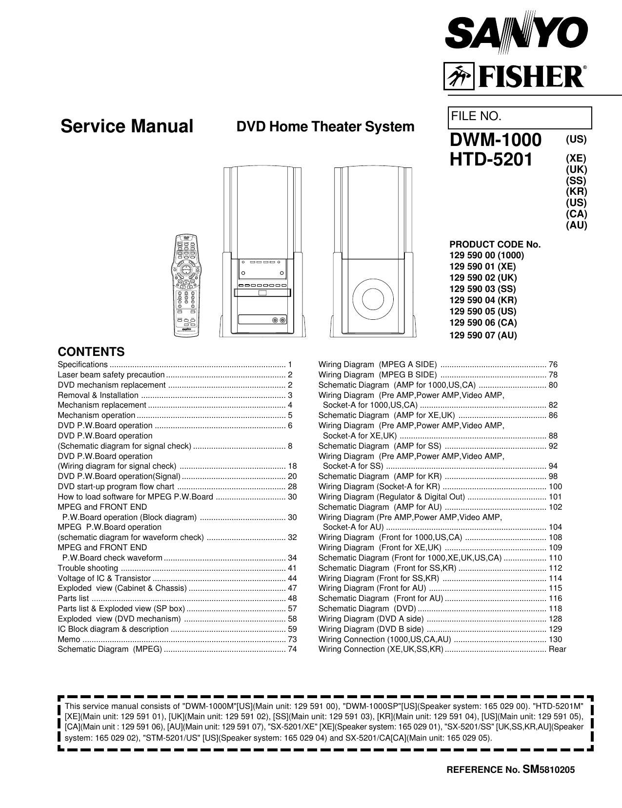
Fisher DWM 1000 Service Manual

This is the 63 pages manual for Fisher DWM 1000 Service Manual.
Read or download the pdf for free. If you want to contribute, please mail your pdfs to info@audioservicemanuals.com.

Page: 1 / 63
left right
Fisher DWM 1000 Service Manual

Extracted text from Fisher DWM 1000 Service Manual (Ocr-read)


Page 1

Service Manual

DVD Home Theater System

SA/WYO

frFlSHER

FILE NO.

DWM-1000
HTD-5201

PRODUCT CODE No.
129 590 00 (1000)
129 590 01 (XE)

129 590 02 (UK)

129 590 03 (SS)

129 590 04 (KR)

129 590 05 (US)

( I 129 590 06 (CA)

@

O O
| III II
( @
I
CONTENTS
Specifications ....................... . 1
Laser beam safety precaution. . 2
DVD mechanism replacement . 2
Removal & Installation .. . 3
Mechanism replacement .4
Mechanism operation .5
DVD P.W.Board operation .6

DVD P.W.Board operation

(Schematic diagram for signal check) ......................................... 8
DVD P.W.Board operation
(Wiring diagram for signal check) ............................................... 18

DVD P.W.Board operation(Signal).
DVD start-up program flow chart
How to load software for MPEG P.W.Board
MPEG and FRONT END


P.W.Board operation (Block diagram) ...................................... 3O
MPEGI P.W.Board operation
(schematic diagram for waveform check) ................................... 32
MPEG and FRONT END

P.W.Board check waveform ...................................................... 34

Trouble shooting
Voltage of IC & Transistor.
Exploded View (Cabinet & Chassis
Parts list ......................................

Parts list & Exploded view (SP box)
Exploded View (DVD mechanism)
IC Block diagram & description
Memo
Schematic Diagram (MPEG)

.57
.58

129 590 07 (AU)

Wiring Diagram (MPEG A SIDE) ..
Wiring Diagram (MPEG B SIDE) ..
Schematic Diagram (AMP for 1000,US,
Wiring Diagram (Pre AMP,Power AMP, deo AMP,

Socket-A for 1000,US,CA) ...........
Schematic Diagram (AMPforXE,UK) .
Wiring Diagram (Pre AMP,Power AMP,VIdeo AMP,

Socket-A for XE,UK) ........................
Schematic Diagram (AMPfor SS)
Wiring Diagram (Pre AMP,Power AMP,VIdeo AMP,

Socket-A for SS) ..............................
Schematic Diagram (AMP for KR)
Wiring Diagram (Socket-A for KR) .
Wiring Diagram (Regulator & Digital Out) .
Schematic Diagram (AMP forAU)
Wiring Diagram (Pre AMP,Power AMP,VIdeo AMP,

Socket-A for AU) ....................................................................... 104
Wiring Diagram (Front for 1000,US,CA) 108
Wiring Diagram (Front for XE,UK) 109
Schematic Diagram (Front for 1000,XE,UK,US,CA 110
Schematic Diagram (Front for SS,KR) . . 112
Wiring Diagram (Front for SS,KR) . . 114
Wiring Diagram (Front for AU) 115
Schematic Diagram (Front for AU) 116
Schematic Diagram (DVD) .. . 118
Wiring Diagram (DVD A side) . 128
Wiring Diagram (DVD B side) .. . 129
Wiring Connection (1000,US,CA,AU) 130
Wiring Connection (XE,UK,SS,KR)....


.101
102

(US)

(XE)
(UK)
(55)
(KR)
(US)
(CA)
(AU)

. Rear

f_______________________________________
I This service manual consists of "DWM-1000M"[US](Main unit: 129 591 00) "DWM-10008P"[US](Speaker system. 165 029 00). "HTD 5201M"

[XE]( (Main unit: 129 591 01) [UK](Main unit: 129 591 02) [SS](Main unit: 129 591 03), [KR](Main unit: 129 591 04), [US](Main unit: 129 591 05)
I [CA](Main unit: 129 591 06) [AU](Main unit:129 591 07) "sx- 5201/XE" [XE](Speaker system: 165 029 01) "sx- 5201/33" [UK 33, KR AU](Speaker
I sysIem: 165 029 02), "STM- 5201/US" [US](Speaker system: 165 029 04) and sx- -5201/CA[CA](Main unit: 155 029 05).

I.--I

REFERENCE No. SM5810205

Page 2

SPECIFICATIONS

Main unit with Main Speaker
Amplifier Section

US>

Main Amplifier

Continuous minimum sine wave RMS power output
per channel at 1kHz into 6 ohms with no more than
10 % total harmonic distortion . 30 Watts

Subwoofer Amplifier

Continuous minimum sine wave RMS power output at
100Hz into 6 ohms with no more than 10 % total
harmonic distortion 30 Watts

General

Output power
Total power : 90W
Main Amplifier: 30 X 2 (at 6 ohms, 10% distortion)
Subwoofer Amplifier : 30W (st 6 ohms, 10% distortion)

Input level and impedance:

VIDEO: VIDEO IN : 1.0 Vp-p (75 ohms)
AUDIO IN (UR): 600 mV/50k ohms
AUX/TV (L/R): 600 mV/50k ohms
Outputs:

MAIN SPEAKER (L/R): 6 ohms
SUBWOOFER: 6 ohms
PHONES:8-32 ohms (XE,UK,SS,KR,AU)
DIGITAL OUT: Optical
AV EURO CONNECTOR : For Euro-AV Cable (XE,UK)
COMPONENT VIDEO OUT: CB/CR: 0.7 Vp-p (75 )
Y: 1.0 Vp-p (75 )

MONITOR VIDEO OUT: 1.0 Vp-p (75 ohms)
AUDIO OUT (L/R): 600 mV (1 kohms)
S-VIDEO OUT: Y: 1.0 Vp-p (75 ohms)NTSC

Y: 1.0 Vp-p (75 ohms)PAL

C: 0.286 Vp-p (75 ohms)NTSC

C: 0.3Vp-p (75 ohms)PAL

DVD Video Player Section
Type: DVD/CD player
Playback standard : PAL or NTSC
Laser: Semiconductor laser. wavelength 650 nm
Laser output (Continuous wave max.)
1 mW (DVD)
0.5mW (CD)
Frequency range (digital audio):
4 Hz to 44 kHz (DVD fs: 96 kHz)
Signal to noise ratio: More than 105 dB
Harmonic distortion (digital audio): 0.003 °/o
Wow and flutter: Below measurable level

Main Speaker (magnetic shield)

Unit used: 10cm ( 4" diameter), Cone type
Maximum music power handling capacity: 60 Watts
Nominal impedance: 6 ohms

General

Power requirements: AC 120V, 60HZ (1000,US,CA)
AC 230V, 50HZ (XE,UK)
AC 230-240V,50HZ (AU)
AC 220V, 60HZ (KR)

Power consumption: 100 Watts
1.4W (standby mode)
Dimensions (W x H X D):Approx. 200(W) x 400(H) x 320(D) mm
Approx. 7.9" x 15.9" x 12.6"
Weight: :Approx.8.7 kg (19.4 lbs)

Main Speaker with Subwoofer (magnetic shield)
Main Speaker

Unit used: 10cm (4" diameter), Cone type

Maximum music power handling capacity: 60 Watts(peak)
Nominal impedance: 6 ohms

Subwoofer

Unit used: 13cm ( 5.1 diameter), Cone type

Maximum music power handling capacity: 60 Watts (peak)
Nominal impedance: 6 ohms

General

Dimensions (W x H x D): Approx 200(W) x 400(H) x 320(D) mm
Approx. 7.9" x 15.9" x 12.6"

Weight: Approx. 5.8 kg (13.2 lbs)

IMPORTANT INFORMATION

Because its products are subject to continuous improvement,
SANYO reserves the right to modify product designs and
specifications without notice and without incurring any obligation.

Specifications subject to change without notice.

Page 6

MECHANISM OPERATION
1.How to setting the TRAY

1. Move the SLIDE left side.

2. Match the Hole of GEAR ® and Hole of CHASSIS GD.

LARG E TOOTH

GREASE
EM-SOL

/ RIB

®
GEAR HOLE

@

GREASE

GREASE
EM-SOL
3. Match the mark of GEAR ® and mark of GEAR @, and then
install the BOSS.
4. Turn the GEAR ® counterclockwise, and then SLIDE move
right side.
5. The GEAR (D move from side to side.

E4

0C)

CHASSIS
FRONT SIDE

MARKER

6. Match the hole of GEAR (D and hole of chassis while turning
GEAR @.

7. Match the mark of LOADING GEAR @ and gear of TRAY
where see horn hole @ of tray.

8. Push a TRAY with the state that turned the entire surface of a
TRAY into approximately 5 degrees the lower part slowly.

MARKER

MARKER LOARDING
GEAR
l

Page 16

PARTS LIST

PRODUCT SAFETY NOTICE
EACH PRECAUTION IN THIS MANUAL SHOULD BE FOLLOWED DURING SERVICING. COMPONENTS IDENTIFIED WITH THE IEC
SYMBOL At IN THE PARTS LIST AND THE SCHEMATIC DIAGRAM DESIGNATED COMPONENTS IN WHICH SAFETY CAN BE OF
SPECIAL SIGNIFICANCE. WHEN REPLACING A COMPONENT IDENTIFIED BY A , USE ONLY THE REPLACEMENT PARTS DESIGNATED,
OR PARTS WITH THE SAME RATINGS OF RESISTANCE, WATTAGE OR VOLTAGE THAT ARE DESIGNATED IN THE PARTS LIST
IN THIS MANUAL. LEAKAGE-CURRENT OR RESISTANCE MEASUREMENTS MUST BE MADE TO DETERMINE THAT EXPOSED
PARTS ARE ACCEPTABLY INSULATED FROM THE SUPPLY CIRCUIT BEFORE RETURNING THE PRODUCT TO THE CUSTOMER.

CAUTION : Regular type resistors and capacitors are not listed. To know those values, refer to the schematic diagram.
Regular type resistors are less than 1/4 W Carbon type and Chip type resistors.
Regular type capacitors are less than 50 V and less than 1000 uF type of Ceramic type, Electrical type and Chip type.

PACKING & ACCESSORIES REF.NO. PART No. DESCRIPTION
REF.N0. PART No_ DESCRIPTION 1-11 645 048 5168 CUSHION,M|D RANGE
614 315 8875 CARTON 0.43511000) 2 514 315 8127 ASSY,GRILLE(1000,XE,UK,SS,KR,AU)
614 317 9688 CARTON CASE(XE) 2 614 317 3250 ASSY,GRILLE(US)
614 317 9686 CARTON CASE(UK) 2 614 318 3648 ASSY,GRILLE(CA)
614 318 0760 CARTON CASE(SS) 3 614 315 6611 BUTTON11000,XE,UK,SS,KR,AU)
614 318 6366 CARTON CASE(KR) 3 614 317 3274 BUTTON(US,CA)
614 317 3328 CARTON CASE(US) 4 614 315 6727 MOUNTINGPANEL
614 318 3853 CARTON CASE(CA) 5 614 315 8134 ASSY,PANEL,FRONT(1000,XE,UK,AU)
614 318 6373 CARTON CASE(AU) 5 514 318 0708 ASSY,PANEL,FRONT(SS,KR)
614 278 9117 NOTICE(1000,US) 5 614 317 3267 ASSY,PANEL,FRONT(US,CA)
614 303 7484 LABEL,CAUTION,CUSHION TOP(1000) 6 614 315 6642 CHASSISMECHA/TRANS/PWB
614 315 9001 INSTRUCTION,MANUAL(1000) 7 614 315 6666 DEC.WINDOW,FL
614 317 9785 INSTRUCTION MANUAL(XE) 8 614 315 7762 HOLDER,TRANS
614 317 9818 INSTRUCTION MANUAL(UK) 8 614 315 6734 MOUNTINC,PWB,JACK PWB FIX
614 318 0845 INSTRUCTION MANUAL(SS) 10 614 310 3837 MOUNTING.FAN
614 318 5434 INSTRUCTION MANUAL(KR) 11 614 315 6765 PANEL,REAR(1000)
614 317 3359 INSTRUCTION MANUAL(US) 11 614 317 5445 PANEL.REAR(XE)
614 318 3807 INSTRUCTION MANUAL(CA) 11 614 317 5452 PANELIREAFKUK)
614 318 5441 INSTRUCTION MANUAL(AU) 11 614 317 5468 PANEL,REAR(SS)
614 317 9801 INSTRUCTION MANUAL,(GREEK)(XE) 11 614 318 6182 PANELREAFKKR)
614 317 3182 INSTRUCTION SHEET,OUICI< GUIDE 11 614 317 3298 PANELIREAWUS)
(1000) 11 514 318 3678 PANEL,REAR(CA)
614 317 3366 INSTRUCTIONSHEETOUICK GUIDE 11 614 318 6199 PANEL-REAR(AU)
(Us) 12 514 314 7107 SHIELD,MPEG PWB BOTTOM
614 315 8874 CUSHION,TOP 13 614 314 7114 SHIELD,MPEG PWB TOP
614 315 8981 CUSHIONBOTTOM 14 514 315 6786 SHIELD,DVD MECHABOTTOM
645 046 8278 POLY SHEET-1300x0500NC,SET 15 614 315 6802 SHIELD.DVD MECHA.TOP
(1000,UK,SS,KR,US,CA,AU) 16 514 307 2538 LABEL,INDICATION,I=USE(1000)
645 047 3418 POLY SHEET-1300X0500NC,SET(XE) 17 614 315 8110 ASSYDEC ESCUTCHEON
645 044 9413 REMOCON,RB-H520MT(1000,CA) (1000,XE,UK,SS,KR,AU)
645 044 9420 REMOCON,RB-H5201ST(XE,UK,AU) 17 614 317 3243 ASSY,DECIESCUTCHEONtUsfiA)
645 044 9437 REMOCON,RB-H5201(SS,KR) 18 6141291901 FIXEHAC CORD
645 046 8381 REMOCON,REM-H5201(US) or 614 2841884 FIXERAC CORD
645 043 9735 BATTERY COVERSERVICE PART 19 614 318 0166 SPACER,SHEET,CHASSIS
645041 1373 CABLE,V|DEO,V|DEO-CABLE(1.5M) (1000,US,CA)
645 047 0355 WIREyMAIN 3p 19 514 317 2884 SPACERSHEETCHASSIS
645 047 0363 WIRESUB WOOFER (XE,UK,SS,KR,AU)
645 017 2175 PLUG,ADAPTOR AC(SS) 20 614129 9136 LUG.LEAD FIX
or 645 006 4630 PLUG,ADAPTOR AC(SS) 21 614 315 6628 BUTTONISELECNSSIKR)
22 514 317 5438 KNOBROTARYMIC/ECHO VOL(SS,KR)
CABINET & CHASSIS 614 317 3080 LABEL,SAFETY(XE,UK,AU)
REF.NO. PART NO. DESCRIPTION
1 614 315 8515 ASSY,CABINET(1000,UK,SS,KR,AU) FIXING PARTS
1 614 317 9481 ASSYICABINEVXE) REF.NO. PART NO. DESCRIPTION
1 614 317 3235 ASSY,CABINET(US.CA) Y01 411 021 3503 SCR S-TPG BIN 3X10,
1-1 614 318 0523 ASSY.BOX,SPEAKER MOUNTINCPANEL
1'2 645 043 4957 LEFT SIDE COVER Y02 411 021 3503 SCR S-TPG BIN 3x10,FRONT PWB
1'3 645 048 4964 RIGHT SIDE COVER Y03 645 046 8208 SCREW,HEAT SINK UNIT
1'4 645 043 4988 MID RANGE HOLDER Y04 545 046 8216 SCREw,PANEL FRONT SIDE
1-5 645 048 4971 RUBBER CATCHEH Y05 645 046 8261 SCREw,PANEL REAR
1'5 645 043 5015 MID RANGE Y06 411 021 6405 SCR S-TPG BIN 3X8,
1-7 645 048 5084 JOIN WIRE MPEG PWBSHIELD MPEG
1'8 645 043 5138 SCREWVSIDE COVER Y07 411 021 3503 SCR S-TPG BIN 3X10,MPEG UNIT
1-9 645 048 5121 SCREW,M|D RANGE HOLDER Yog 411 020 3905 SCR S_TPG BRZ+FLG 3x10,
1-10 645 048 5081 SCREWMID RANGE UNIT DVD MECHA

.43.

Page 39

IC BLOCK DAIGRAM & DESCRIPTION
IC110,111,117 EM636165TS,KM416$1120DT, K4S161622D (1 Mega x 16 Synchronous DRAM(SRAM))

Symbol Type Description

CLK Input Clock: CLK is driven by the system clock. All SDRAM input signals are sampled on
the positive edge of CLK: CLK also increments the internal burst counter and controls
the output registers.

CKE Input Clock Enable: CKE activates(HlGH) and deactivates(LOW) the CLK signallf CKE
goes low synchronously with clock(seteup and hold time same sa other inputs), the
internal clock is suspended from the next clock cycle and the state of output and
burst address is frozen as long as the CKE remains low: When both banks are in the
idle state, deactivating the clock controls the entry to the Power Down and Self Refresh
modes. CKE is synchronous except after the device enters Power Down and Self
Refresh modes, where CKE becomes asynchronous until exiting the same mode.
The input buffers, including CLK, are disabled during Power Down and Self Refresh
modes, providing low standby power.

A11 Input Bank Select: A1 1 (BS) defines to which bank the BankActivate, Read. Write, or
BankPrecharge command is being applied.

ACPAIO Input Address Inputs: A07A10 are sampled during the BankActivate command (row address
A07A10 and Read/Write command (column address AOVA7 with A10 defining Auto
Precharge) to select one location out of the 256K available in the respective bank.
During a Precharge command, A10 is sampled to determine if both banks are to be
precharged (A107HIGT). The address inputs also provide the oprcode during a Mode
Register Set command:

CS# Input Chip Select: CS)? enables (sampled LOW) and disables (sampled HIGH) the command
decoder: All commands are masked when 08:: is sampled HIGH. CSI! provides for
external bank selection on systems with multiple banks. It is considered part of
the command code.

RAS# Input Flow Address Strobe: The RAS# signal defines the operation commands in conjunction
with the CAS# and WE# signals and is latched at the positive edges of CLK. When
RAS# and CS# are asserted "LOW" and CAS# is asserted "HIGH," either the
BankActivate command or the Precharge command is selected by the WE# signal.
When the WE# is asserted "HIGH," the BankActivate command is selected and the
bank designated by BS is turned on to the active state: When the WE# is asserted
"LOW," the Precharge command is selected and the bank designated by BS is
switched to the idle state after the precharge operation.

CAS# Input Column Address StrobezThe CAS# signal defines the operation commands in
conjunction with the RAS# and WE# signals and is latched at the positive edges of
CLK: When RAS# is held "HIGH" and CS# is asserted "LOW, the column access is
started by asserting CAS#"LOW." Then, the Read or Write command is selected by
asserting WE# "LOW" or "HIGH."

WE# Input Write Enable: The WE# signal defines the operation commands in conjunction with
the RAS# and CAS# signals and is latched at the positive edges of CLK. The WE#
input is used to select the BankActivate or Precharge command and Read orWrite

command:
LDQM, Input Data Input/Output Mask: LDQM and HDQM are byte specific, nonpersistent l/O buffer
UDQM controls.The I/O buffers are placed in a highrz state when DQM is sampled HIGH:

Input data is masked when DOM is sampled HIGH during a write cycle. Output data
is masked (tworclock latency) when DQM is sampled HIGH during a read cycle.
UDQM masks DQtSPDQB, and LDQM masks DQ77DQO.

DQCPDQ15 lnput/ Data l/O: The D0045 input and output data are synchronized with the positive edges
Output of CLK. The l/Os are bytermaskable during Reads and Writes.

NC , No Connect:These pins should be left unconnected.

VDDQ Supply DQ Power: Provide isolated power to DOS for improved noise immunity.(3:3V:0.3V)

Vsso Supply DO Ground: Provide isolsted ground to DQs for improved noise immunity.(0V)
VDD Supply Power Supply: +3.3V:O:3V

Vss Supply Ground

.71.