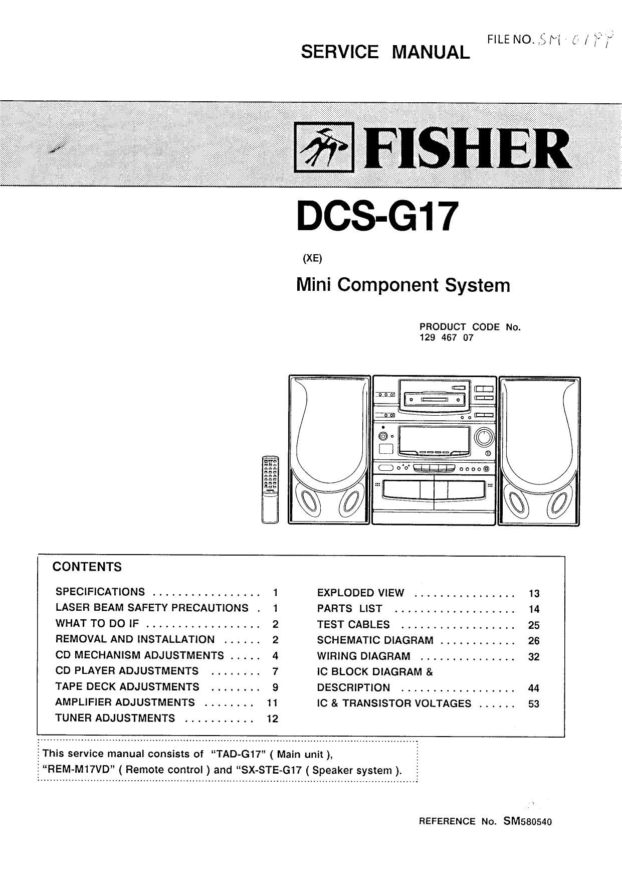
Fisher DCSG 17 Service Manual

This is the 40 pages manual for Fisher DCSG 17 Service Manual.
Read or download the pdf for free. If you want to contribute, please mail your pdfs to info@audioservicemanuals.com.

Page: 1 / 40
left right
Fisher DCSG 17 Service Manual

Extracted text from Fisher DCSG 17 Service Manual (Ocr-read)


Page 1

FILE NO. ,8 M / 35' f

SERVICE MANUAL

DCS-G1 7

(XE)

Mini Component System

PRODUCT CODE No.
129 467 07

iI


I mum-nu
I mum-om
I cannon

CONTENTS
SPECIFICATIONS ................. 1 EXPLODED VIEW ................ 13
LASER BEAM SAFETY PRECAUTIONS . 1 PARTS LIST ................... 14
WHAT TO DO IF .................. 2 TEST CABLES .................. 25
REMOVAL AND INSTALLATION ...... 2 SCHEMATIC DIAGRAM ............ 26
CD MECHANISM ADJUSTMENTS ..... 4 WIRING DIAGRAM ............... 32
CD PLAYER ADJUSTMENTS ........ 7 IC BLOCK DIAGRAM &
TAPE DECK ADJUSTMENTS ........ 9 DESCRIPTION .................. 44
AMPLIFIER ADJUSTMENTS ........ 11 IC & TRANSISTOR VOLTAGES ...... 53
TUNER ADJUSTMENTS ........... 12

IThis service manual consists of TAD-G17" ( Main unit ),

REM-M17VD ( Remote control ) and SX-STE-G17 ( Speaker system ).

REFERENCE No. SM580540

Page 2

SPECIFICATIONS

Note:

The below mentioned specifications are mainly based on the IHF measurements standard.

They can therefore not directly be compared with specifications based on the DIN standard or other standards.

TUNER SECTION
Frequency range FM :87.5 - 108.0 MHz

MW ; 522 - 1,611 kHz

LW : 144 288 kHz

CASSETTE DECK SECTION

Track system ....... 4 track, 2»channel stereo
Frequency response . . 50 Hz - 14,500 Hz (Cr02 type)
50 Hz - 13,500 Hz (Normal type)
60 dB (Dolby NR ON)

0.12 % (WRMS)

Signal to noise ratio
Wow & Flutter

Tape speed ........ 4,75 cm/sec
Fast forward and
rewind time Approx. 110 sec. ((2-60)
CD PLAYER SECTION
Channels .......... 2-channel stereo
Sampling frequency 441 kHz
Pick-up ............ Optical 3-beam semiconductor laser
Laser output ........ 0.6 mW (Continuous wave max.)
Wave length ........ 790 nm

Frequency response . .
Wow & Flutter

20 HZ - 20,000 Hz

AMPLIFIER SECTION
Output power .......
Sound preset
Inputs .............
Outputs

GENERAL
Power requirements ..
Power consumption .
Dimensions (WxHxD) .
Weight ............
SPEAKER SYSTEMS

Type ..............
Unit used

20 W x 2 ( at 4 ohms, 10%
distortion )

Four electronic presets
VIDEO IN : 400 mV/50k ohms
SPEAKER : 4 ohms

PHONES :8 - 32 ohms

AC :230 V, 50 Hz

75 W

Approx. 270 x 330 x 285 mm
Approx. 6.5 kg

3 way bass reflex

Woofer: 13 cm cone type
Mid range :5 cm cone type
Tweeter : piezoelectric

Maximum power-handling capacity 40 W (peak)

Nominal impedance
Dimensions (WxHxD)
Weight ............

4 ohms
Approx. 180 x 330 x 209 mm
Approx. 2.7 kg (per speaker)

Below measurable limits

LASER BEAM SAFETY PRECAUTIONS

Specifications subject to change without notice.

I Pick-up that emits a laser beam is used in this CD player.

CAUTION:
USE OF CONTROLS OR ADJUSTMENTS
OR PERFORMANCE OF PROCEDURES
OTHER THAN THOSE SPECIFIED
HEREIN MAY RESULT IN HAZARDOUS
RADIATION EXPOSURE

LASER OUTPUT ..... 0.6 mW Max. (CW)
WAVELENGTH ...... 790nm

w I LA§R PRUJUCT
LAERLMTE

CAUTION- INVISIBLE LASER RADIATION WHEN OPEN AND
INTERLQ DEFEATED. D EXP DRE TD BEAM.

ADVAHSEL- usvuua LASER sm LING van wine." "In
SIKKEHHEDSAFBHYDERE ER IIDE AF rummuu uunéA uus mas:
FOR STRALING.

VARNING- osvutm LASER STRALNING mm DENNA DEI. An OPPNAD
ocn SPARE its URKOPPLAD STHALEN' AR FARLIG.

VORSICHT- UNSIDHTBARE LASERSTRANLUNG TRITI' AUS, WENN
DECKEL GEDFFNET UND WENN SICHERHEITSVERRIEGELUNG
DEEQERJCKT IST. NIGHT, DEM STRAHL AUSSETZEN.

VARD~ AVATTAESSA .IA SUDJALUKITUS DHITETTAES§A DLET ALTI'IINA

NAKYMATTOMALLE LASEHSATEILYLLE. ALA KATSO SATEESEEN

_1_

Page 3

WHAT TO DO IF

It the operation of the unit or display is not normal, RESET

or you wish to clear the contents of the memory. %
1. Disconnect the power cord.

. Press the RESET button for at least 20 seconds.

. Connect the power cord.

. Press the POWER button to turn the power on.

wa

REMOVAL AND INSTALLATION


Disconnect the power cords plug from the electrical outlet.
All wiring should be returned to the original position after work is completed
First have ready many the new FIXERS (614 129 2496) for replacement,
Arrange the lead wires so that they are not near the heat sink.

a. CABINET

(1) Remove the 5 rear panel mounting screws. (GD)
(2) Remove the 2 cabinet mounting screws (G)

b. REAR PANEL

(1) Remove the 8 rear panel mounting screws. (®)
(2) Remove the 2 stand mounting screws. (®)