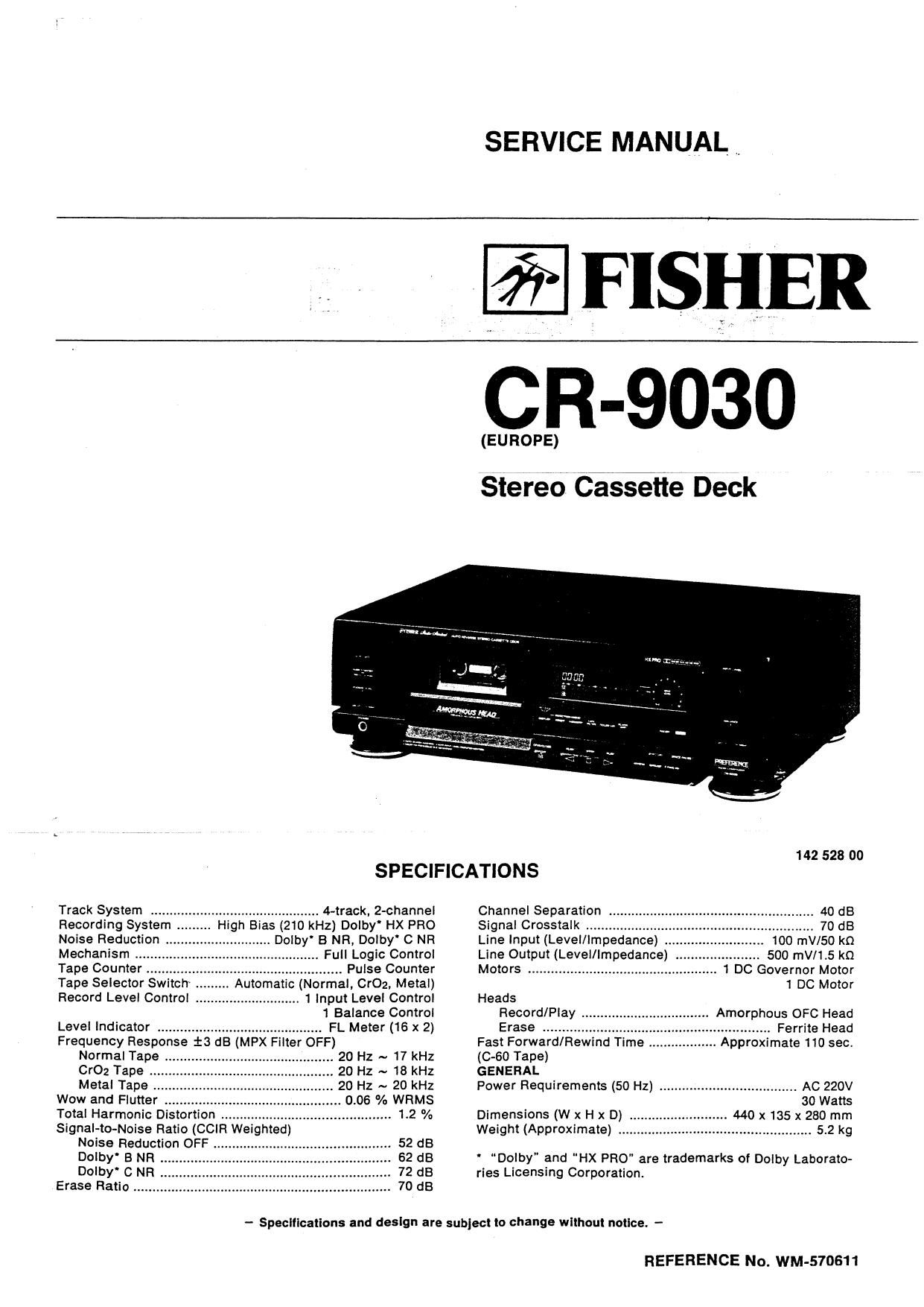
Fisher CR 9030 Service Manual

This is the 25 pages manual for Fisher CR 9030 Service Manual.
Read or download the pdf for free. If you want to contribute, please mail your pdfs to info@audioservicemanuals.com.

Page: 1 / 25
left right
Fisher CR 9030 Service Manual

Extracted text from Fisher CR 9030 Service Manual (Ocr-read)


Page 1

SERVICE MANUAL ,_

FISHER

CR-9030

(EUROPE)

Stereo CaSEfie Deck

SPECIFICATIONS

............................ 4-track, 2-channel
High Bias (210 kHz) Dolby' HX PRO
Dolby' B NR, Doiby' C NR
V Full Logic Control
Pulse Counter
Automatic (Normal. CrOz. Metal)
.. 1 input Level Control

1 Balance Control

Track System
Recording System
Noise Reduction
Mechanism ..
Tape Counter
Tape Selector Switch
Record Level Control .


Level Indicator ............................................ FL Meter (16 x 2)
Frequency Response i3 dB (MPX Filter OFF)
Normal Tape ............................................. 20 Hz ~ 17 kHz
CrOz Tape .


Metal Tape

Wow and Flutter 0.06 % WRMS

Total Harmonic Distortion .......... 1.2 %
Signal-to-Noise Ratio (CCIR Weighted)
Noise Reduction OFF A 52 dB
Dolby" B NR . . 62 dB
Doiby' C NR . . 72 dB
Erase Ratio .. . 70 dB

142 528 00
Channel Separation 40 dB
Signal Crosstalk ...... . 70 dB

100 mV/50 km
500 mV/1t5 kn
1 DC Governor Motor
1 DC Motor

Line Input (Level/Impedance) .
Line Output (Level/Impedance) .
Motors ........................................

Heads
Record/Play .
Erase ........

Fast Forward/Rewind Time

Amorphous OFC Head
........... Ferrite Head
Approximate 110 sec.

(0-60 Tape)

GENERAL

Power Requirements (50 Hz) AC 220V
30 Watts

Dimensions (W x H x D) .......... 440 x 135 x 280 mm

Weight (Approximate) ................... 5.2 kg

' "Dolby" and HX PRO" are trademarks of Dolby Laborato-
ries Licensing Corporation.

- Specifications and design are sublecl to change without notice -

REFERENCE No. WM-570611

Page 9

CASSETTE DECK ADJUSTMENT

BEFORE ADJUSTMENT

it the tape surface which contacts the head, the capstan, the

pinch roller, etc., is stained, it will cause unstable running of

the tape, wow and flutter, imperfect recording and erasing.
deterioration of tonal quality, and even tape jam around the
capstan, etc. Occasionally clean each part as follows;

1. Cut off power.

2. Open the cassette lid.

3. Wipe the head, the capstan, and the pinch roller with a
cotton swab. If they are excessively stained, clean them
with a swab soaked in absolute alcohol or cleaning liquid
available on the market.

MEASURING INSTRUMENTS REQUIRED
Dualtrace Oscilloscope
AC VTVM (AC voltmeter with high impedance)
Dummy Load (47km
' Frequency Counter i 7
Signal Oscillator
Test Tapes
3 12.5kHz Test Tape (Example: A.BEX TOO-154) for
Azimuth Adjustment
: 3kHz Test Tape (Example: TEAC MTT-111) for Tape
Speed Adjustment
; 400Hz Test Tape (Example: TEAC Ml'l'~150) for Play-
back sensitivity Adjustment
Test Tape for Recording and Playback Operations
z Metal Tape (Example: TDK AC 712)
: Cr02 Tape (Example: TDK AC 513)
: Normal Tape (Example: TDK AC 223)

SWITCH POSITIONS
Unless especially indicated, set each switch as follows;
BALANCE
lNPUT LEVEL
MPX FILTER SWItch .
DOLBY NR Switch
HX PRO Switch


TAPE SPEED ADJUSTMENT

1. Connect the dummy load (47km) and the frequency
counter to the LINE OUT terminal L.

2. Load a test tape (Example: TEAC MTI'-111) and set it in
the playback mode.
3. Adjust potentiometer in the capstan motor so that the

output becom es 3000Hz iSHz.

HEAD AZIMUTH ADJUSTMENT

1. Connect the dummy load (47km and the dualtrace oscil-
loscope to the LINE OUT terminals L and R.

2 Load a test tape (Example: A.BEX TOG-154) and set it in
the playback mode.
3. Adjust the head azimuth adjustment screw, so that the

waveforms become maximum on the oscilloscope and
the right wave form overlaps with the left one.

PLAYBACK SENSITIVITY ADJUSTMENT

1. Connect the AC VTVM to the test terminal PB OUT (L) to
GND and PB our (n) to GND.

Load a test tape (Example: TEAC MTT-150) and set it in
the playback mode.

2.

Adjust P101, so that the output of test terminal (775MV,
L) becomes 775mV.
Adjust P102, so that the output of test terminal (775MV,
R) becomes 775mV.

HX PRO DRIVE TRANS ADJUSTMENT

1.

2.

Load a METAL tape (Example: TDK AC 712) and set it in
the Rec. mode.

Connect AC VTVM to the test terminal DTS AJT (L) to GND
and DTS AJT (R) to GND.

Adjust L101, so that the output voltage of DTS AJT (L)
becomes minimum level.

Adjust L102, so that the output voltage of DTS ADT (R)
becomes minimum level.

RECORD BIAS ADJUSTMENT

1.

10.

Connect thalow frchuency oscillator to the'fsidreiof the
LINE IN terminal, and the dummy load (47kt!) and AC
VTVM to the L side of the LINE OUT terminal.

Load a CrOz tape (Example: TDK AC 513) and set it in the
recording mode.

Set the input level volume control to the maximum posi~
tion and set the record balance volume control to the
center position.

Feed the signals of 1kHz and 14kHz at 7mV (-43st)
from the frequency generator into the unit. Then, record
the signals on the tape.

Play back the recorded signals and adjust P107, so that
the difference between output of the 1kHz and 14kHz
signals reaches £0.5dB.

Adjust P108 for the Fl side by following the same proce-
dures as described for the L side.

Load a METAL tape (Example: TDK AC 712) and set it in
the recording mode.

Adjust P103 (L) and P104 (R) following the same proce-
dures as for CrOz tape adjustment.

Load a NORMAL tape (Example: TDK AC 223) and set it
in the recording mode.

Adjust P301 (P301 is common adjustment of L and Ft.)
following the same procedures as for CrOz tape adjust-
ment.

METER SENSITIVITY ADJUSTMENT

1.

2.

Connect the low frequency oscillator to the L side of the
LINE IN terminal.

Feed a signal of 1kHz at 100mV (-20st) from the fre-
quency generator into the unit. Then, adjust INPUT LEVEL
volume so that test terminal (775MV) becomes 775mV.
Connect the AC VTVM to the test terminal METER (L) to
GND and METER (R) to GND.

Adjust P105, so that the output of METER (L) becomes
2.4V.

Adjust P106, so that the output of METER (Fl) becomes
2.4V.

Page 14

P.C.BOARD PARTS LIST (Continued)

:3" Part No. Description Oty 2:" Part No. Description Qty
R198 401 024 7400 CARBON 10K JA 1/6W 1 R392 401 027 1801 CARBON 51K JA 1/6W 1
R199 401 0252305 CARBON 150K JA 116W 1 R393 401 027 1801 CARBON 51K JA 1/6W 1
R200 401 0252305 CARBON 150K JA 1/6W 1 R394 401 025 0004 CARBON 120K JA 1/6W 1
R201 401 026 4605 CARBON 33K JA 1/6W 1 R395 401 027 4504 CARBON 62K JA 1/6W 1
R202 401 026 4605 CARBON 33K JA 1/6W 1 R396 401 028 0308 CARBON 91K JA 1/6W 1
R207 401 014 5201 CARBON 15K JA 1/4W 1 R397 401 027 3003 CARBON 56K JA 1/6W 1
R208 401 014 5201 CARBON 15K JA 1/4W 1 R398 401 026 4605 CARBON 33K JA 1/6W 1
R209 401 0124503 CARBON 100 JA 1/4W 1 R399 401 026 4605 CARBON 33K JA 1/6W 1
R210 401 012 4503 CARBON 100 JA 1/4W 1 R400 401 026 4902 CARBON 330K JA 1/6W 1
R211 401 017 2504 CARBON 27K GA 1/4W 1 R401 401 027 4604 CARBON 62K JA 1/6W 1
R212 401 0125706 CARBON 1K JA 1/4W 1 R402 401 024 7707 CARBON 100K JA 1/6W 1
R213 401 015 4708 CARBON 100K JA 1/4W 1 R403 401 027 5905 CARBON 68K JA 1/6W 1
R214 401 015 4708 CARBON 180K JA 1/4W 1 R404 401 026 7408 CARBON 39K JA 1I6W 1
R215 401 0247707 CARBON 100K JA 1/6W 1 R405 401 027 1801 CARBON 51K JA 1/6W 1
R216 401 024 7707 CARBON 100K JA 1/6W 1 R409 401 011 8908 CARBON 1 JA 1I4W 1
R217 401 024 7707 CARBON 100K JA 1/6W 1
R218 401 024 7707 CARBON 100K JA 1/6W 1 ASSY,PCB,POWER SWITCH
R219 401 012 9300 A CARBON 1M JA 1/4W 1 83 620 211 6013 . Assy,PCB,Power Switch 1
R220 401 012 9300 CARBON 1M JA 1/4W 1 CS3 620 201 6566 Socket.Holder,4P 1
R221 77 4010247707 , CARBON , 100de 1/6W 7 , 1 ' PSW1 "520 0153546 Push Switch 1 Key " ' 1
R222 401 024 7707 CARBON 100K JA 1/6W 1 WR4 620 211 5900 Wire.Jumper,o4S 1
R301 401 012 9300 CARBON 1M JA 1I4W 1
R302 401 012 5708 CARBON 1K JA 1/4W 1 NOTES:
F1303 02 050 9205 FUSIBLE RES 56 JA 1/4W 1 1. Parts order must contain Mode! Number, Part Number and De-
R304 401 027 5908 CARBON 68K JA 1/sw 1 scriplion
5505 2g: 3g; 23g: 53:30: 2:: 1g 32 114 I 2. Oggering quantity of screws and resistors must be multiple of 10
R306 402 061 0805 FUSIBLE RES 10 JA 1I4W 1 p '
or 402 039 2800 FUSIBLE RES 10 JA 114W 1
R309 401 016 8507 CARBON 24K JA 1/4w 1 pfiopucr SAFETY "one:
R310 401 020 2003 CARBON 417K JA 1/4W 1 1 _ _ 1
R311 401 012 5703 CARBON 1K JA 1/4W 1 Each precaution in this manual should be followed during servic-
3512 401 012 7009 CARBON 10K JA 1/4W 1 ing Components identified with the lEC symbol A in the parts list
R313 401 012 5703 CARBON 1K JA 1,41 1 and the schematic diagram designate components in which safety
R314 401 012 7009 CARBON 10K JA 1/4W 1 can be of special significance. When replacing a component iden-
R315 401 020 2003 CARBON 4.7K JA 1/4W 1 tified with A, use only the replacement parts designated, or parts
R316 4010247400 CARBON 10K JA 115W 1 with the same ratings of resistance, wattage or voltage that are
F1317 401 024 7400 CARBON 10K JA 1/6W 1 designated in the parts list in this manuali Leakage-current or re-
3313 401 012 7009 CARBON 10K JA 1/4W 1 sistance measurements must be made to determine that exposed
R322 401 024 7400 CARBON 10K JA 1/6W 1 parts are acceptably insulated from the supply circuit before re-
R323 401 024 7400 CARBON 10K JA 1/6W 1 turning the product ta the customer.
R324 401 0247400 CARBON 10K JA 1/6W 1
R326 401 012 7009 CARBON 10K JA 1/4W 1
R327 401 012 8105 CARBON 100K JA 1/4W 1
R328 401 020 2904 CARBON 47K JA 1/4W 1
R330 401 016 2604 CARBON 220 JA 1/4W 1
R334 401 012 5708 CARBON 1K JA 1/4W 1
R335 401 025 7805 CARBON 2.2K JA 1/6W 1 ,
R341 401 0168002 CARBON 2,4K JA 1/4W 1
R343 401 0221905 CARBON 680 JA 1/4W 1
R347 401 0127009 CARBON 10K JA 114W 1
R361 401 027 0309 CARBON 47K JA 1/5W 1
R362 401 027 0309 CARBON 47K JA 1/5W 1

R363 401024 6403 CARBON 10 JA 1l6W 1
R364 401 024 6403 CARBON 10 JA 1/6W 1
R365 402 061 0805 FUSIBLE RES 10 JA 1/4W 1
or 402 039 2600 FUSlBLE RES 10 JA 1/4W 1
R357 401 016 3809 CARBON 2.2K JA 1/4W 1
R368 401 016 3809 CARBON 2.2K JA 1/4W 1
R369 401 016 3809 CARBON 2.2K JA 1/4W 1
R370 401 016 3809 CARBON 2.2K JA 1/4W 1
R371 401 0125708 CARBON 1K JA 1/4W 1
R372 401 017 1804 CARBON 2.7K JA 1/4W 1
R373 401 014 8301 CARBON 160 JA 1/4W 1
R374 401 012 5708 CARBON 1K JA 1/4W 1
R375 401 012 5708 CARBON 1K JA 1/4W 1
R376 401 016 3809 CARBON 2.2K JA 1/4W 1
R377 401 022 3107 CARBON 6.6K JA 1/4W 1
R378 401 019 1901 CARBON 3.9K JA 1/4W 1
R379 401 016 3809 CARBON 2.2K JA 1/4W 1
R380 401 018 3807 CARBON 3.3K JA 1/4W 1
R381 401 018 3807 CARBON 313K JA 1/4W 1
R382 401 018 3809 CARBON 2.2K JA 1/4W 1
R383 401 012 7009 CARBON 10K JA 1/4W 1
R386 401 021 4105 CARBON 56K JA 1/4W 1
R388 401 027 7407 CARBON 75K JA 1/6W 1
R389 401 027 7407 CARBON 75K JA 1/6W 1
R390 401 027 7407 CARBON 75K JA 116W 1
R391 401 025 6501 CARBON 20K JA 1/6W 1