Fisher CORONET R 1 Service Manual

This is the 7 pages manual for Fisher CORONET R 1 Service Manual.
Read or download the pdf for free. If you want to contribute, please mail your pdfs to info@audioservicemanuals.com.

Page: 1 / 7
left right
Fisher CORONET R 1 Service Manual

Extracted text from Fisher CORONET R 1 Service Manual (Ocr-read)


Page 1

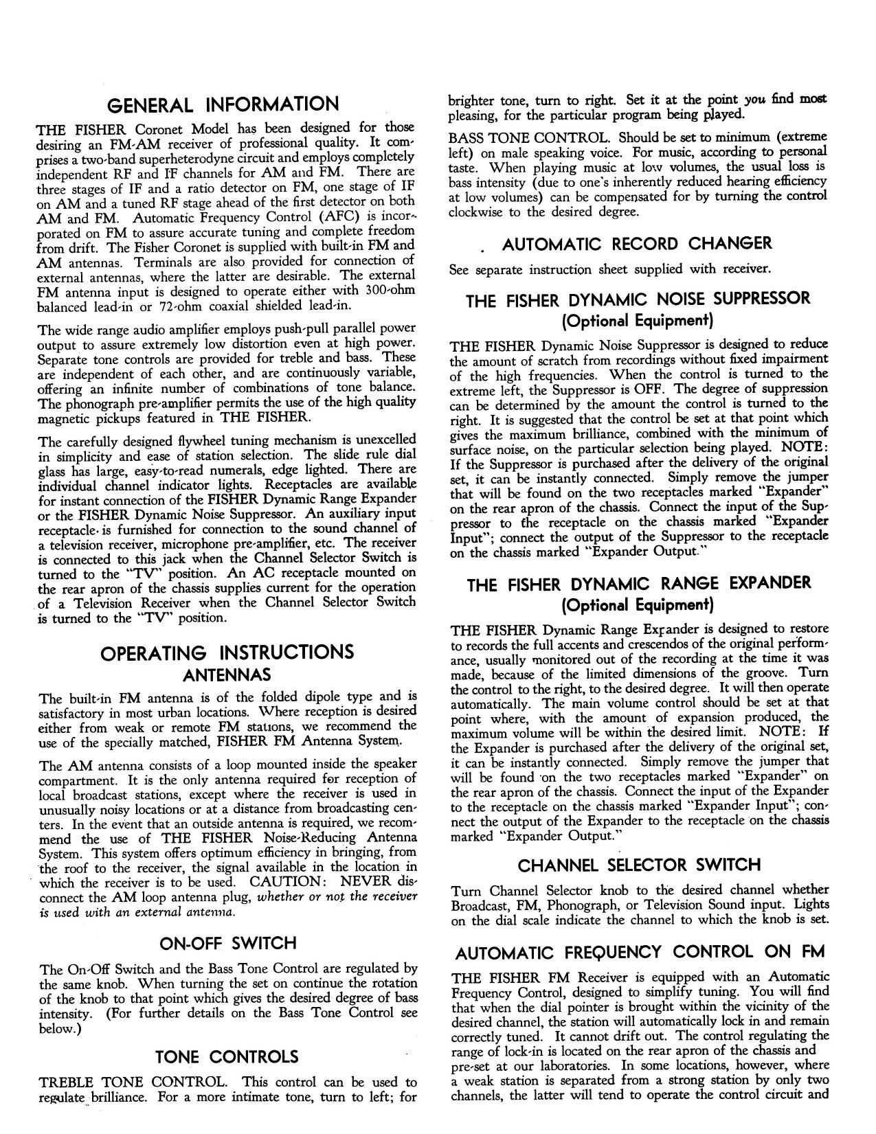
GENERAL INFORMATION

THE FISHER Coronet Model has been designed for those
desiring an FMrAM receiver of professional quality. It com!
prises a twmband superheterodyne circuit and employs completely
independent RF and IF channels for AM and FM. There are
three stages of IF and a ratio detector on FM, one stage of IF
on AM and a tuned RF stage ahead of the first detector on both
AM and FM. Automatic Frequency Control (AFC) is incora
porated on FM to assure accurate tuning and complete freedom
from drift. The Fisher Coronet is supplied with builtin FM and
AM antennas. Terminals are also provided for connection of
external antennas, where the latter are desirable. The external
FM antenna input is designed to operate either with 300ohm
balanced leadrin or 72rohm coaxial shielded Ieadrin.

The wide range audio amplifier employs pushpull parallel power
output to assure extremely low distortion even at high power.
Separate tone controls are provided for treble and bass. These
are independent of each other, and are continuously variable,
offering an infinite number of combinations of tone balance.
The phonograph preramplifier permits the use of the high quality
magnetic pickups featured in THE FISHER.

The carefully designed flywheel tuning mechanism is unexcelled
in simplicity and ease of station selection. The slide rule dial
glass has large, easytOrread numerals, edge lighted. There are
individual channel indicator lights. Receptacles are available
for instant connection of the FISHER Dynamic Range Expander
or the FISHER Dynamic Noise Suppressor. An auxiliary input
receptacle- is furnished for connection to the sound channel of
a television receiver, microphone preamplifier, etc. The receiver
is connected to this jack when the Channel Selector Switch is
turned to the TV" position. An AC receptacle mounted on
the rear apron of the chassis supplies current for the operation
of a Television Receiver when the Channel Selector Switch
is turned to the TV" position.

OPERATING INSTRUCTIONS
ANTENNAS

The builtrin FM antenna is of the folded dipole type and is
satisfactory in most urban locations. \Vhere reception is desired
either from weak or remote FM stations, we recommend the
use of the specially matched, FISHER FM Antenna System.

The AM antenna consists of a loop mounted inside the speaker
compartment. It is the only antenna required for reception of
local broadcast stations, except where the receiver is used in
unusually noisy locations or at a distance from broadcasting cenr
ters. In the event that an outside antenna is required, we recom
mend the use of THE FISHER Noise'Reducing Antenna
System. This system offers optimum efliciency in bringing, from
the roof to the receiver, the signal available in the location in

' which the receiver is to be used. CAUTION: NEVER dise
connect the AM loop antenna plug, whether or not the receiver
is used with an external antenna.

ON-OFF SWITCH

The On»Oif Switch and the Bass Tone Control are regulated by
the same knob. When turning the set on continue the rotation
of the knob to that point which gives the desired degree of bass
intensity. (For further details on the Bass Tone Control see
below.)

TONE CONTROLS

TREBLE TONE CONTROL. This control can be used to
regulateqbrilliance. For a more intimate tone, turn to left; for

brighter tone, turn to right. Set it at the point you find most
pleasing, for the particular program being played.

BASS TONE CONTROL. Should be set to minimum (extreme
left) on male speaking voice. For music, according to personal
taste. When playing music at low volumes, the usual loss is
bass intensity (due to ones inherently reduced hearing efficiency
at low volumes) can be compensated for by turning the control
clockwise to the desired degree.

AUTOMATIC RECORD CHANGER

See separate instruction sheet supplied with receiver.

THE FISHER DYNAMIC NOISE SUPPRESSOR
(Optional Equipment)

THE FISHER Dynamic Noise Suppressor is designed to reduce
the amount of scratch from recordings without fixed impairment
of the high frequencies. When the control is turned to the
extreme left, the Suppressor is OFF. The degree of suppression
can be determined by the amount the control is turned to the
right. It is suggested that the control be set at that point which
gives the maximum brilliance, combined with the minimum of
surface noise, on the particular selection being played. NOTE:
If the Suppressor is purchased after the delivery of the original
set, it can be instantly connected. Simply remove the jumper
that will be found on the two receptacles marked Expander"
on the rear apron of the chassis. Connect the input of the Supr
pressor to the receptacle on the chassis marked Expander
Input"; connect the output of the Suppressor to the receptacle
on the chassis marked Expander Output.

THE FISHER DYNAMIC RANGE EXPANDER
(Optional Equipment)

THE FISHER Dynamic Range Expander is designed to restore
to records the full accents and crescendos of the original perform;
ance, usually monitored out of the recording at the time it was
made, because of the limited dimensions of the groove. Turn
the control to the right, to the desired degree. It will then operate
automatically. The main volume control should be set at that
point where, with the amount of expansion produced, the
maximum volume will be within the desired limit. NOTE: If
the Expander is purchased after the delivery of the original set,
it can be instantly connected, Simply remove the jumper that
will be found 'on the two receptacles marked Expander on
the rear apron of the chassis. Connect the input of the Expander
to the receptacle on the chassis marked Expander Input; con-
nect the output of the Expander to the receptacle on the chassis
marked Expander Output.

CHANNEL SELECTOR SWITCH

Turn Channel Selector knob to the desired channel whether
Broadcast, FM, Phonograph, or Television Sound input. Lights
on the dial scale indicate the channel to which the knob is set.

AUTOMATIC FREQUENCY CONTROL ON FM

THE FISHER FM Receiver is equipped with an Automatic
Frequency Control, designed to simplify tuning. You will find
that when the dial pointer is brought within the vicinity of the
desired channel, the station will automatically lock in and remain
correctly tuned. It cannot drift out. The control regulating the
range of lock'in is located on the rear apron of the chassis and

prerset at our laboratories. In some locations, however, where
a weak station is separated from a strong station by only two
channels, the latter will tend to operate the control circuit and

Page 2

make it diflicult to bring in the weak station. Should this occur,
turn the Automatic Frequency Control (knurled brass shaft on
the rear apron of the chassis) counter clockwise to the degree
necessary to eliminate the above condition.

ALIGNMENT PROCEDURE
AM IF ALIGNMENT

NOTE: For the following IF and RF adjustments the signal
generator should be readjusted as necessary to maintain the
output below 2 volts across the voice coil. .

1. With the Selector Switch in the Broadcast position, set the
tuning capacitor for maximum capacity.

2. Feed a 455 Kc amplitude modulated signal to the signal grid

of the 613136 converter tube. (pin 7 of V9) through a 0.1
mfd capacitor.

3. Set the Volume Control at maximum.
4. Connect an output meter across the speaker voice coil.

5. Adjust the top and bottom cores of the lst and 2nd IF trans,
formers (Z5 and 2:6) for maximum. If noise causes exces'
sive meter deflection, the Volume Control should be turned
down slightly.

BROADCAST ALIGNMENT

1. With the tuning capacitor completely closed, set the pointer
to the index mark on the dial. (The first graduation mark
appearing at the extreme left of the dial scale markings.)

2. Connect an amplitude modulated signal generator to the
AM antenna terminals. A 200 mmfd capacitor should be
inserted between the high" side of the generator lead and
the antenna terminal.

3. Set the dial and signal generator to 1400 Kc.

4. Adjust the Broadcast oscillator, RF and antenna coil trim!
mers (C43, C41 and Cr36 respectively) for maximum.

5. Set the dial and signal generator to 600 Kc.

6. Adjust the Oscillator, RF and antenna coil cores (L9, L8
and L7 respectively) for maximum.

7. Reset the dial and signal generator to 1400 Kc and repeat
step 4 if necessary.

FM DETECTOR ALIGNMENT

NOTE: For all of the following IF and RF adjustments the
output of the signal generator should be readjusted as necessary
to maintain the voltage at test point A (shown on schematic)
between 8 and 9 volts dc.

1. Rotate the Selector Switch to the FM position.
2. Connect an electronic voltmeter between the chassis and the

positive side of the 4 mid electrolytic capacitor, C34. (Test
point A on the schematic diagram.)

Feed an unmodulated 10.7 Mc signal through a .1 mfd
capacitor to the (SBAG FM detectorrdrive grid (pin 1 on V6.)

in

4. Tune the FM detector primary (bottom of 214) forsmaxi'
mum. -

5. Disconnect the electronic voltmeter from the 4 mfd capacitor
and connect to the FM detector audio output (test point B
on schematic diagram.)

6. Tune the FM detector secondary (top of 2,4) for zero.

FM IF ALIGNMENT

1 Feed an unmodulated 10.7 Mc signal through a 500 to 1000
mmfd capacitor to the grid of the RF amplifier tube (pin
1 of V4.)

2. Connect the electronic voltmeter to test point A as in step
2 above.

3. Align the top and bottom cores of the lst, 2nd and 3rd IF
coils (Zel, 22 and Zr} respectively) for maximum.

FM RF ALIGNMENT

NOTE: For the following adjustments the AFC circuit should
be disabled by turning the AFC control (R113) fully counter
clockwise.

1. Set the dial to 106 Mc.

2. Feed a 106 Mc unmodulated signal to the SOC/ohm FM
antenna terminals with a 120 ohm composition resistor conr
nected in series with each lead of the signal generator.

3. Connect the electronic voltmeter to test point A.

4. Adjust the oscillator, RF and antenna trimmers (012, C37
and (3.3 respectively) for maximum. For optimum adjust!
ment rock the tuning capacitor back and forth while adjust;
ing the RF trimmer.

NOTE

THE FOLLOWING ADJUSTMENTS HAVE BEEN
MADE AT THE FACTORY AND SELDOM REQUIRE
REALIGNMENT EXCEPT WHEN COILS AND COMr
PONENTS IN THE FM RADIOrFREQUENCY SECTION
HAVE BEEN REPLACED.

5. Set the signal generator to 90 Mc and tune the receiver for
maximum as indicated on the electronic voltmeter.

6. If the dial calibration is oil more than .2 Mc at 90 Mc, set
the dial to 90 Mc and adjust the core in the FM oscillator
coil (L14) for maximum. (On model R11, compress or
spread the oscillator coil winding.)

7. Adjust the cores in the RF and antenna coils (L3 and LI
respectively) for maximum.

8. Reset the dial and signal generator to 106 Mc and repeat
step 4.

9. Set the signal generator to 90 Mc and tune the receiver for
maximum. If calibration has shifted as a result of step 8,
repeat steps 6, 7 and 8.

10. If the receiver was badly out of alignment, step 9 may have
to be repeated more than once.

AT YOUR SERVICE

It is our continuing desire that you enjoy THE FISHER to its
utmost capabilities. Should you have any questions with regard
to its operation after you have had an opportunity to familiarize
yourself with the instrument, wont you please write us? In
any event, let us know how it is meeting your requirements.
Replacement parts that may be needed should be ordered by
giving model number; serial number, part number and customr
er's name. Shipment can be made promptly if these details
are complete.