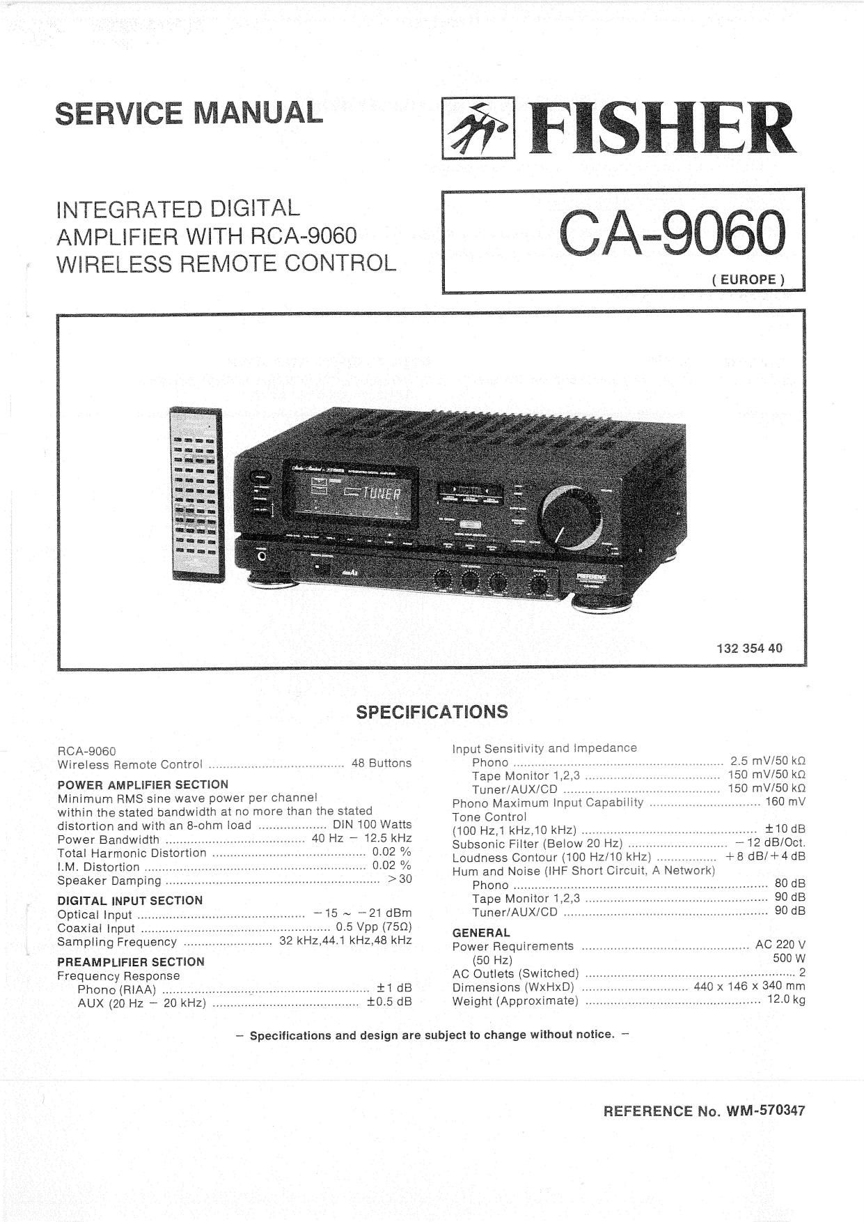
Fisher CA 9060 Service Manual

This is the 28 pages manual for Fisher CA 9060 Service Manual.
Read or download the pdf for free. If you want to contribute, please mail your pdfs to info@audioservicemanuals.com.

Page: 1 / 28
left right
Fisher CA 9060 Service Manual

Extracted text from Fisher CA 9060 Service Manual (Ocr-read)


Page 1

SERVICE MANUAL

INTEGRATED DlGITAL
AMPLIFIER WITH RCA-9060
WIRELESS REMOTE CONTROL

FISHER

CA-906O

( EUROPE )
132 354 40
SPECIFICATIONS
RCA-9060 input Sensitivrty and impedance
Wireless Remote Control ,,,,, r .......... . . 48 Buttons Phono .V . ... .. .7 . 2 5 mV/50 k0
Tape Monitor 1,2.3 . , 150 mV/SO kQ
POWER AMPL'F'ER SECTION Tuner/AUX/CD ...... , 150 mm kn

Minimum RMS sine wave power per channel

within the stated bandwidth at no more than the stated
distortion and with an B-ohm load DIN 100 Watts
Power Bandwidth ............. 40 Hz * 125 kHz
Total Harmonic Distortion , 0.02 °/u
IM. Distortion ................. , 0.02 %
Speaker Damping ........................ . >30

DIGITAL INPUT SECTION
Optical input ..
Coaxial Input .
Sampling Frequency r
PREAMPLIFIER SECTION
Frequency Response

Phone (RIAA)
AUX (20 Hz 7 20


. -15 ~ ~91 dBrn
0.5 Vpp (75m
32 kHz,44tl kHz/18 kHz


....................... 11 dB
........................ 10.5 dB

Phono Maximum lnput Capability .H 160 mV
Tone Control
(100 HZ,1kHZ,1O kHz) .. i10 dB


Subsonic Filter (Below 20 Hz) . #12 dB/Oct.
Loudness Contour (lOO Hz/lO kHz) . +8 dBl-l-4dB
Hum and Noise (iHF Short Circuit, A
Phone ................... 80 dB
Tape Monitor 1,2,3 90 dB
Tuner/AUX/CD .. 90 dB
GENERAL
Power Requirements . . AC 220 V
(50 HZ) 500 W
AC Outlets (Switched) ,. .......................... 2
Dimensions (WxHXD) 440 x146 x 340 mm
Weight (Approximate) .. . 120 Kg

- Specifications and design are subject to change without notice. -

REFERENCE No. WM-570347

Page 2

POWER AMPLIFIER ADJUSTMENT

BEFORE ADJUSTMENT

Unplug the AC power cord and set the front panel controls as follows:

a Power switch to OFF position.

0 Set the SPEAKERS switch to the OFF position.

0 Turn the MASTER VOLUME Control to mlnimum.

o IDLING CURRENT ADJUSTMENT VR301/VR302 (on the Main P.C.Board) setting to mechanical center position.
0 Connect the AC power cord and Power switch to the ON position,

IDLING CURRENT ADJUSTMENT

This adjustment is very sensitive to changes in ambient temperature. Allow set to operate for 2 minutes before attempting this
alignment.

LEFT CHANNEL AMPLIFIER RIGHT CHANNEL AMPLIFIER

1. Connect the DC Voltmeter between Test Point TP1 and 1 Connect the DC Vultmeter between Test Point TP2 and
TPS on the Main P.C.Board, TP4 on the Main FC.Boardi

2. Adjust the VR301 for an indication of 15mV iSmV on th 2. Adjust the VR302 for an indication of 15mV 1-5mv on the
DC Voltmeter. - DC Voltmeter.

ADJUSTMENT POINTS

a: 01 04 02

MS 39C )® 3%:
> > (

TF3 rm nu TP2
LEFT CHANNEL RIGHT CHANNEL