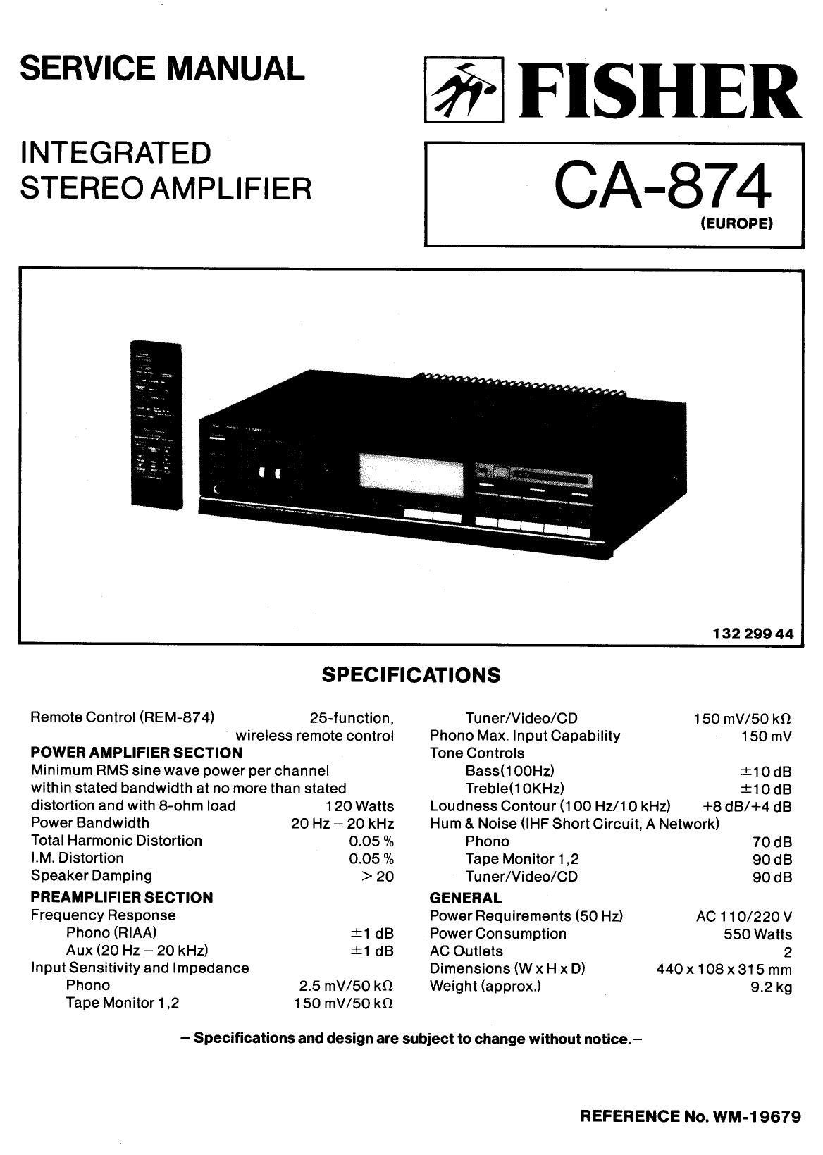
Fisher CA 874 Service Manual

This is the 20 pages manual for Fisher CA 874 Service Manual.
Read or download the pdf for free. If you want to contribute, please mail your pdfs to info@audioservicemanuals.com.

Page: 1 / 20
left right
Fisher CA 874 Service Manual

Extracted text from Fisher CA 874 Service Manual (Ocr-read)


Page 1

SERVICE MANUAL

INTEGRATED
STEREO AMPLIFIER

FISHER

CA-874

(EUROPE)
132 299 44
SPECIFICATIONS
Remote Control (REM-874) 25-function, Tuner/Video/CD 150 mV/50 kn
wireless remote control Phono Max. Input Capability 150 mV
POWER AMPLIFIER SECTION Tone Controls
Minimum RMS sine wave power per channel Bass(100Hz) :10dB
within stated bandwidth at no more than stated Treble(1OKHz) :10 dB
distortion and with 8-ohm load 120 Watts Loudness Contour (100 Hz/10 kHz) +8 dB/+4 dB
Power Bandwidth 20 Hz - 20 kHz Hum & Noise (lHF Short Circuit, A Network)
Total Harmonic Distortion 0.05 % Phono 70 dB
I.M. Distortion 0.05 % Tape Monitor 1 ,2 90 dB
Speaker Damping > 20 Tuner/Video/CD 90 dB
PREAMPLIFIER SECTION GENERAL
Frequency Response Power Requirements (50 Hz) AC 110/220 V
Phono (RIAA) :1 dB Power Consumption 550 Watts
Aux (20 Hz - 20 kHz) i1 dB AC Outlets 2
Input Sensitivity and Impedance Dimensions (W x H x D) 440 x108 x 315 mm
Phono 2.5 mV/SO k0 Weight (approx) 9.2 kg
Tape Monitor 1,2 150 mV/50 k9

- Specifications and design are subject to change without notice.-

REFERENCE No. WM-1 9679

Page 2

CABINET 8: CHASSIS EXPLODED VIEW

POWER AMPLIFIER ADJUSTMENT

BEFORE ADJUSTMENT
Unplug the AC power cord and set the front panel controls as follows:

Power switch to OFF position.
Set the SPEAKERS switch to the OFF position.
Set the volume level to minimum level by Pressing theVOLUME DOWN button.

IDLING CURRENT ADJUSTMENT VR501/VR502 (on the Main Amplifier P.C.Board) setting to mechanical center
DOSI IOn.

Connect the AC power cord and Power Switch to the ON position.

IDLING CURRENT ADJUSTMENT

This adjustment is very sensitive to changes in ambient temperature. Allow set to operate for 2 minutes
before attempting this alignment.

LEFT AMPLIFIER RIGHT AMPLIFIER

1) Connect the DC Voltmeter between Pins 19 and 21 on 1) Connect the DC Voltmeter between Pins 20 and 22 on
the Main Amplifier P.C.Board. the Main Amplifier P.C.Board.

2) Adjust the VR501 for an indication of 9mV (7mV 2) Adjust the VR502 for an indication of 9mV (7mV
~15mV) on the DC Voltmeter. ~15mV) on the DC Voltmeter.

_2_