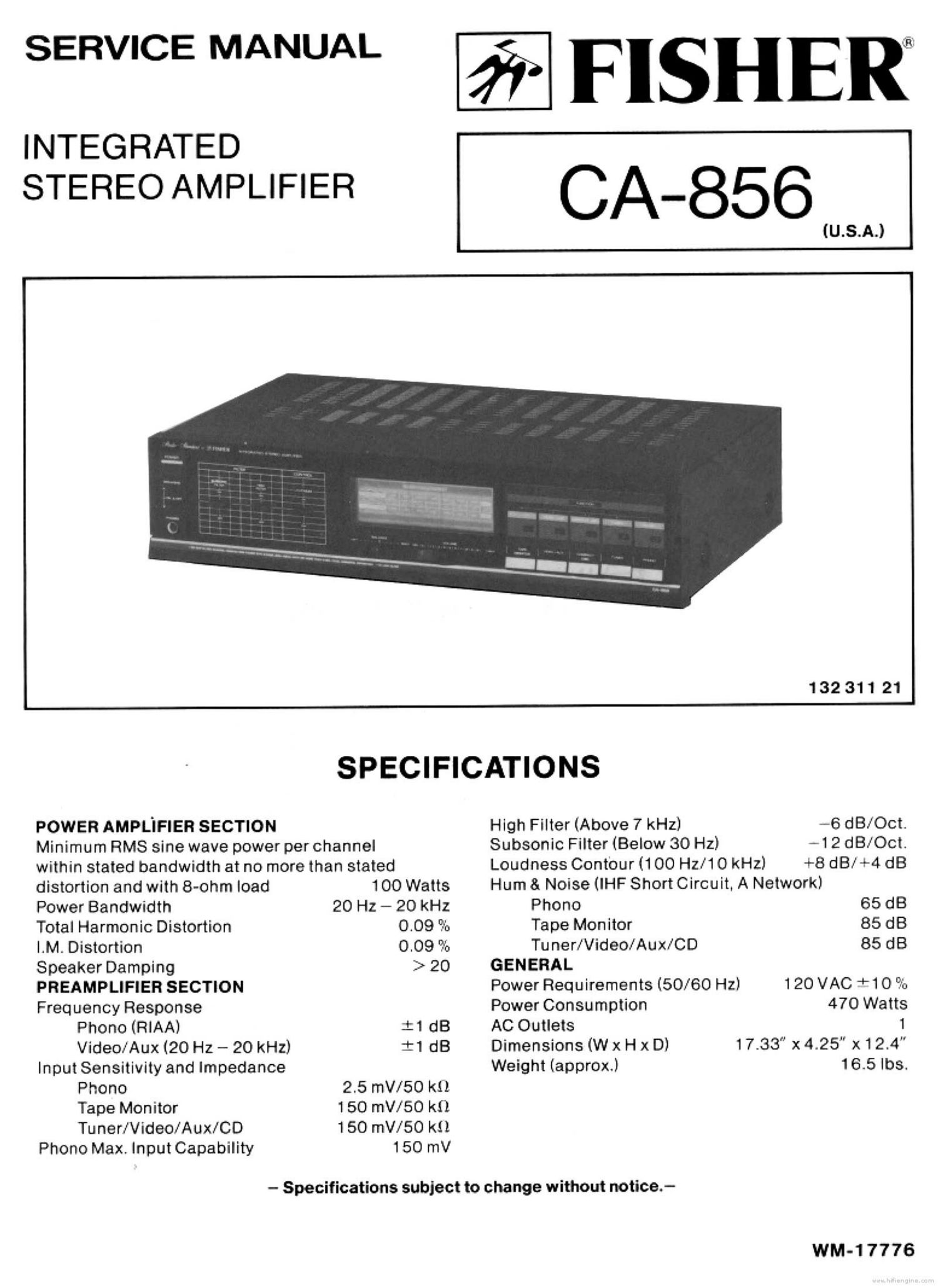
Fisher CA 856 Service Manual

This is the 17 pages manual for Fisher CA 856 Service Manual.
Read or download the pdf for free. If you want to contribute, please mail your pdfs to info@audioservicemanuals.com.

Page: 1 / 17
left right
Fisher CA 856 Service Manual

Extracted text from Fisher CA 856 Service Manual (Ocr-read)


Page 1

SERVICE MANUAL - FISHE

INTEGRATED

STEREO AMPLIFIER C A_856

IU.S.A.)

132311 21

SPECIFICATIONS
POWER AMPLIFIER SECTION High Filter (Above 7 kHz) -6 dB/Oct.
Minimum RMS sine wave power per channel Subsonic Filter (Below 30 Hz) -1 2 dBrOct.
within stated bandwidth at no more than stated Loudness Contour (100 Hz/10 kHz) +8 dB/+4 dB
distortion and with 8-ohm load 100 Watts Hum 8. Noise (IHF Short Circuit. A Network)
Power Bandwidth 20 Hz - 20 kHz Phono 65 dB
Total Harmonic Distortion 0.09 It; Tape Monitor 85 dB
|.M. Distortion 0.09 as Tu ner/Video/Aux/CD 85 dB
Speaker Damping > 20 GENERAL
PREAMPLIFIEB SECTION Power Requirements (50/60 Hz) 120 VAC +10 it.
Frequency Response Power Consumption 470 Watts
Phono (RIAA) :1 dB AC Outlets 1
VideorAux (20 Hz - 20 kHz} :1 dB Dimensions (W x H x D) 17.33 x 4.25" x124"
Input Sensitivity and Impedance Weight (approx.) 16.5le.
Phono 2.5 mV/5O kt).
Tape Monitor 1 50 mil/50 k0
Tu ner/Video/Aux/CD 150 mV/SO k1!
Phono Max. Input Capability 150 mV

- Specifications subject to change without notice.-

WM-17776

Page 2

CONTENTS

Functional Block Diagram ....................................................................... 2
Cabinet & Chassis Exploded View ............................................................ 3,4
Cabinet 8 Chassis Parts List .................................................................... 5
Power Amplifier Adjustment ..................................................................... 6
Integrated Circuit Block Diagram ............................................................. 6.7
P.C.Board Parts List .................................................................... 8,9,10,11
Printed Circuit Board (Bottom View) ................................................... 12.13.14
PointtoPointWiringDiagram ................................ 15.16
Schematic Diagram .......................................................................... 17,18
Semiconductor Lead Identification ............................................................ 19

FUNCTIONAL BLOCK DIAGRAM

FUNCTION
E0. Amp. ON

PHONO @ . 010

on .
TUNER©-o-<:\o
OFF
ON .
co @ ..
cko OFF

AUX ON .
VIDEO OFF

TAPE © ..
REC our

BALANCE VOLUME

I
E Orr

Model Eo-ase I
TAPE Graphic E0. Amp.

MON'TOR I Hthilter
° : ' g
5 III I
I

-l

O 0
Graphic EO. VFl. . .
L __________ J Low Filter
f
TAPE
PLAY BACK Meter Drive IC A}, p0wc,
A Level Meter
W
Speaker
System

A

Power Amp Speaker -
Selector .
. Protector

Protector FUSE
Circuit

Flighl
LOUDNESS Charm Headphone