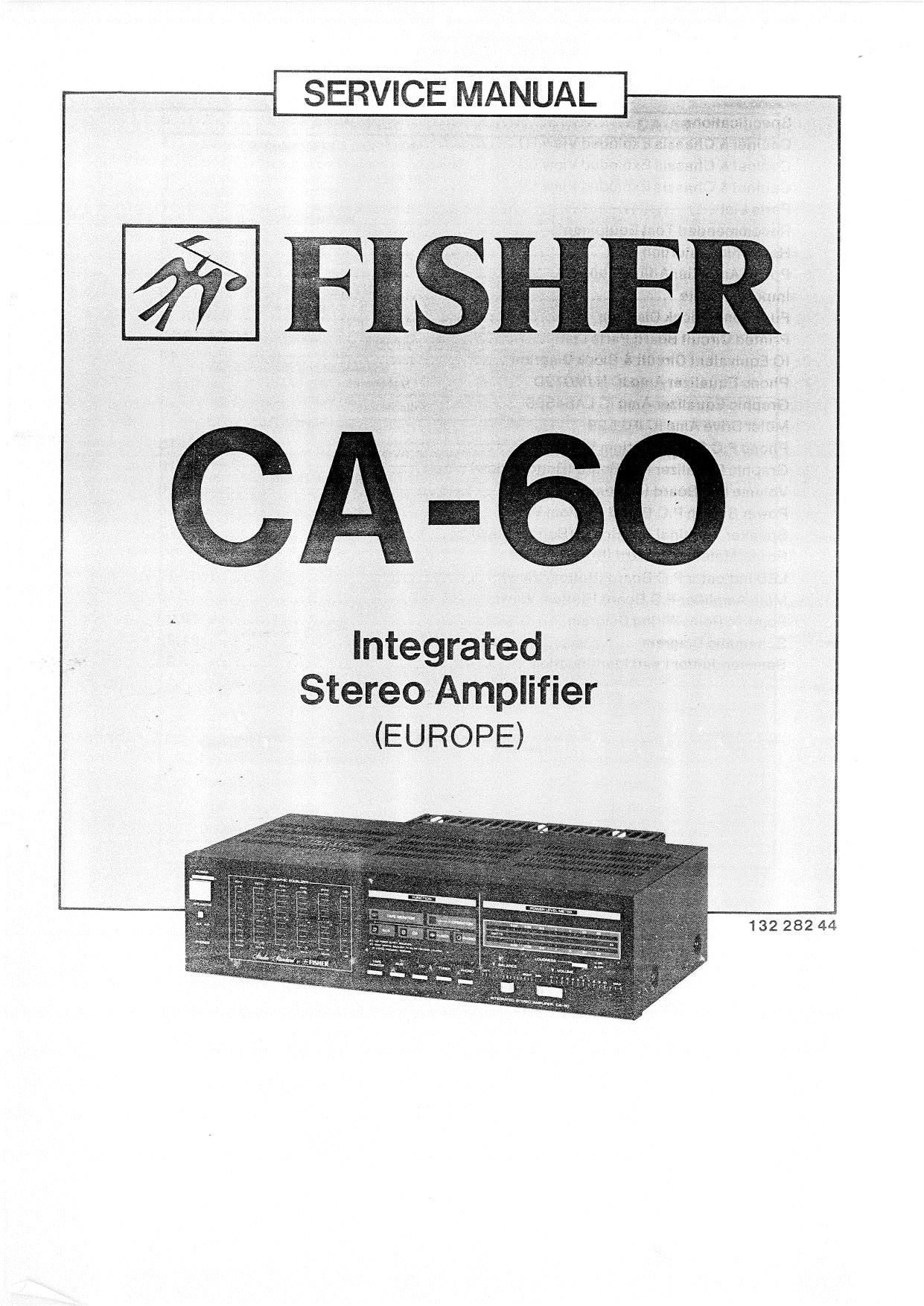
Fisher CA 60 Service Manual

This is the 20 pages manual for Fisher CA 60 Service Manual.
Read or download the pdf for free. If you want to contribute, please mail your pdfs to info@audioservicemanuals.com.

Page: 1 / 20
left right
Fisher CA 60 Service Manual

Extracted text from Fisher CA 60 Service Manual (Ocr-read)


Page 1

SERV!CE MANUAL

Integrated
Stereo Amplifier
(EUROPE)

132 282 44

Page 2

CONTENTS

Specifications ............................................................................. 3
Cabinet 8. Chassis Exploded View (1) .................................................... 4
Cabinet & Chassis Exploded View (2) .................................................... 5
Cabinet & Chassis Exploded View (3) .................................................... 6
Parts List ................................................................................... 7
Recommended Test Equipments ......................................................... 8
Harmonic Distortion Test ................................................................. 8
Power Amplifier Adjustment .............................................................. 9
Important Note ............................................................................. 9
Functional Block Diagram ................................................ I ............... 9
Printed Circuit Board Parts List .............................................. 10,11,12,13
10 Equivalent Circuit 8. Block Diagram .................................................. 14

Phone Equalizer Amp IC NJMO72D
Graphic Equalizer Amp IC LA64588
Meter Drive Amp IC lFl2E29

Phono P.C.Board (Bottom View) ..................................................... .. . .. 15
Graphic Equalizer P.C.Board (Bottom View) ............................................ 15
Volume P.C.Board (Bottom View) ........................................................ 16
Power Switch P.C.Board (Bottom View) ................................................. 16
Speaker Terminal P.C.Board (Bottom View) ............................................ 17
Power Meter P.C.Board (Bottom View) .................................................. 17
LED Indicator P.CtBoard (Bottom View) ................................................. 17
Main Amplifier P.C.Board (Bottom View) ................................................ 18
PointTo Point Wiring Diagram ....................................................... 19,20
Schematic Diagram .................................................................. 21,22

Semiconductor Lead identification ............ , ......................................... 23

4)