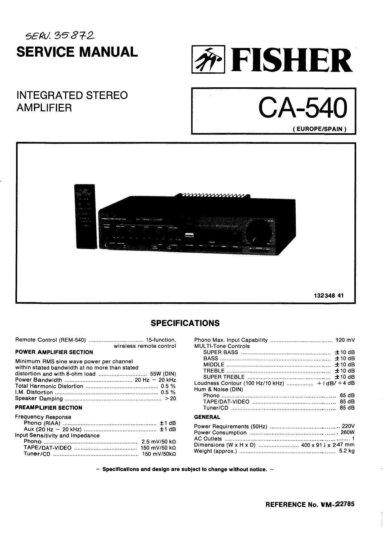
Fisher CA 540 Service Manual

This is the 12 pages manual for Fisher CA 540 Service Manual.
Read or download the pdf for free. If you want to contribute, please mail your pdfs to info@audioservicemanuals.com.

Page: 1 / 12
left right
Fisher CA 540 Service Manual

Extracted text from Fisher CA 540 Service Manual (Ocr-read)


Page 1

6512M 558-712
SERVICE MANUAL

INTEGRATED STEREO
AMPLIFIER

FISHER

CA-54O

( EUROPE/SPAIN )

132348 41
SPECIFICATIONS
Remote Control (HEM-540) .................................. 15-function, Phono Max. Input Capability ...................................... 120 mV
wireless remote control MULTI-Tone Controls
POWER AMPLIFIER SECTION SUPER BASS . 110 dB

Minimum RMS sine wave power per channel
within stated bandwidth at no more than stated
distortion and with B-ohm load ......... 55W (DIN)
Power Bandwidth 20 Hz - 20 kHz
Total Harmonic Disto o .. 05 /0
I.M. Distortion ...... 0.5 %
Speaker Damping . >20
PREAMPLIFIER SECTION
Frequency Response

Phono (RIAA) .............. . :I:1 dB

Aux (20 Hz - 20 kHz) . . :I:1 dB
Input Sensitivity and Impedance

Phono ................... 2.5 mV/50 k0
TAPE/DAT-VIDEO 15o mV/50 kQ
Tuner/CD ............. . 150 mV/SOkQ

BASS .. :l: 10 dB

MIDDLE . $10 dB

TREBLE . 110 dB

SUPER TREBLE .. :10 dB
Loudness Contour (100 Hz/1O kHz) . + IdB/ +4 68
Hum & Noise (DIN)

Phone . 65 dB


TAPE/D DEC 85 dB
Tuner/CD ............... . 85 dB
GENERAL
Power Requirements (50Hz) . 220V
Power Consumption . . 260w
AC Outlets ................... .. 1

400 X 91 S x
...................... 5.2 kg

Dimensions ( .
Weigh! (approx.) .............

- SpeciIicalions and design are subiect Io change wllhoul noIIce. -

REFERENCE No. VIM -22785

Page 2

CABINET & CHASSIS EXPLODED VIEW

POWER AMPLIFIER ADJUSTMENT

BEFORE ADJUSTMENT

Unplug the AC power cord and set the front panel controls as follows:

Power Switch to OFF position.
Set the SPEAKERS Switch to the OFF position.
Turn the MASTER VOLUME Control to minimum.

Connect the AC power cord and Power Switch to the ON position.

IDLING CURRENT ADJUSTMENT
This adjustment is very sensitive to changes in ambient temperature. Allow set to operate for 2 minutes before attempting this
alignment.

LEFT CHANNEL AMPLIFIER

1t

2.

Connect the DC Voltmeter between pins TP1 and TP2 on
the Main P.C.Board.

Of the DC Voltmeter indicates less than amv. Cut the lead
wire of the resistor R303 (560!» in the Main P.CBoard.
After cutting the R303, and if less than 3mv, the 10201
(pPC1298V) has anything wrong so repairment is re-
quired.

After cutting the R303, and if more than 2DmV. the Power
Transistor (0201,0203) has anything wrong so
repairment is required.

0t less than 20mV, the Main Amplifier Circuit is a normal
operation.

RIGHT CHANNEL AMPLIFIER

1.

2.

Connect the DC Voltmeter between pins TP3 and TP4 on
the Main P.C.Board.

01 the DC Voltmeter indicates less than 3mV, Cut the lead
wire of the resistor R304 (560m in the Main P.C.Board.
After cutting the R304, and if less than 3mV, the ICZOZ
(uPC1298V) has anything wrong so repairment is re-
quired.

After cutting the R304, and it more than 20mV, the Power
Transistor (0202,0204) has anything wrong so
repairment is required.

0f less than 20mv, the Main Amplifier Circuit is a normal
operation.