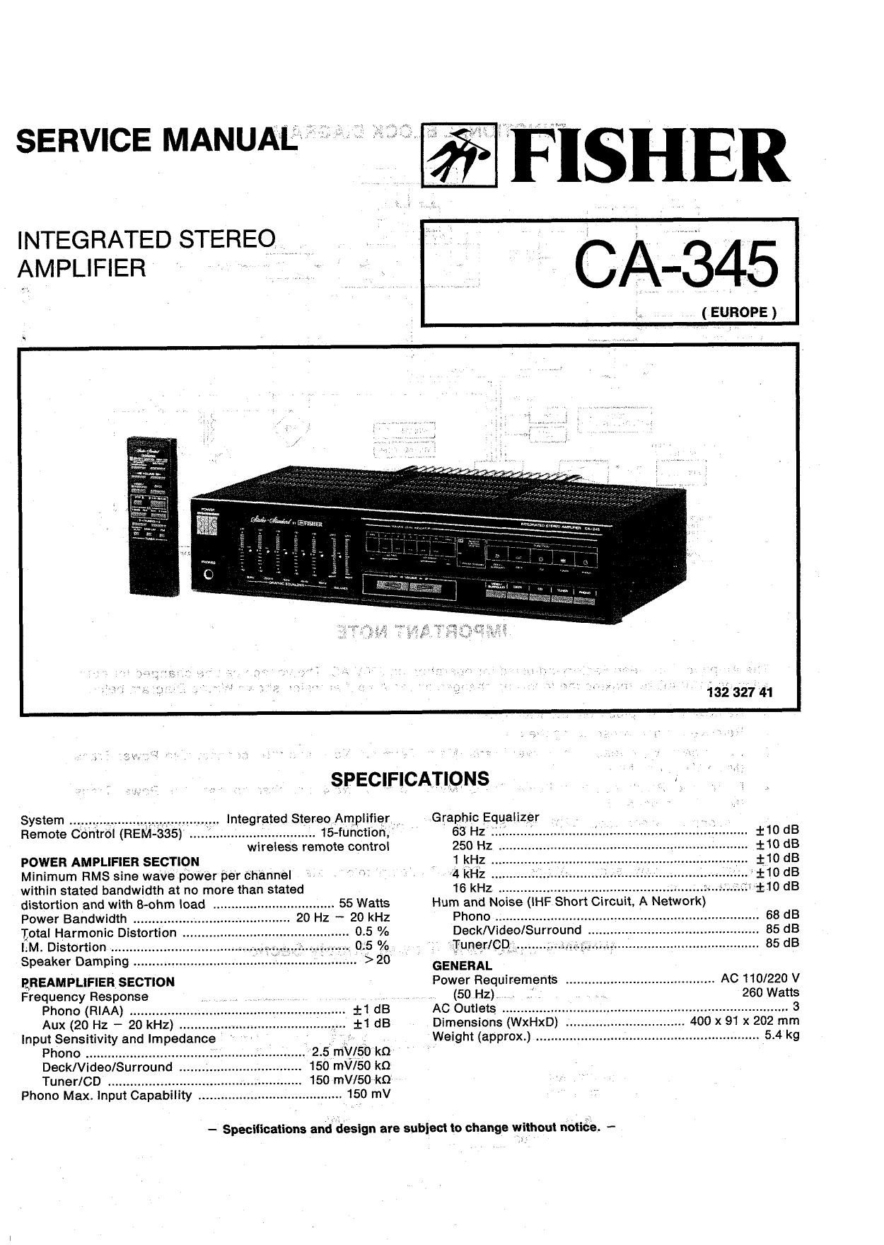
Fisher CA 345 Service Manual

This is the 14 pages manual for Fisher CA 345 Service Manual.
Read or download the pdf for free. If you want to contribute, please mail your pdfs to info@audioservicemanuals.com.

Page: 1 / 14
left right
Fisher CA 345 Service Manual

Extracted text from Fisher CA 345 Service Manual (Ocr-read)


Page 1

SERVICE MANUAE

INTEGRATED STEREQ
AMPLIFIER ' '

FISHER

CA-345

, ( EUROPE )

132 327 41


....................... 15-fUnction,
wireless remote controi

Remote Contrdl (REM-335)

POWER AMPLIFIER SECTION

Minimum FIMS sine wavepower per channel

within stated bandwidth at no more than stated

distortion and with 8-ohm load .. ........... 55 Watts
Power Bandwidth ............. 20 Hz - 20 kHz
total Harmonic Distortion
I.M. Distortion
Speaker Damping

EREAMPLIFIER SECTION
Frequency Response
Phone (RIAA) ...........
Aux (20 Hz - 20 kHz) .
Input Sensitivity and Impedance
Phono ..........................
Deck/Video/Surround .
Tuner/CD ....................
Phono Max. Input Capability ..


v2.5,my/5o kn
150 mV/SO ko
150 mV/50 ka
150 mV


Integrated Stereo Amplifier ._

AspECIFICATlQ-NS

Graphic Equalizer
63 Hz '
250 Hz i
1 kHz
*4 kHz
16 kHz .

Hum and Nonse (
Phono ........................
DeckNideo/Surround
rIunerlCQ;.....i..;.,.


GENERAL

Power Requirements ........................................ AC 110/220 V
(50 Hz) ' , 260 Watts

AC Outlets ......................................... 3

Dimensions (WxHxD) . 400 x 91 x 202 mm

Weight (approx) . 5.4 kg

- Specifications and design are subiect to change without msuée. «-
I»,

Page 2

FUNCTIONAL BLOCK DIAGRAM

GRAPHIC EELVDLUME I
so . AMP.

PHDND O
r GRAPHIC Eo. AMP.
men O---* POWER AMP.
cm 0-. BALANCE m7535 .
- were WE Savoy-cease
DECK 545 we
[RID O-- LC782l "if Jr

5 0-" ELECTRIC VOLUE
[we O-->
we O----
VIDEO/SURRDUND ® 6
PNDND
TEES}?
» FUNCTION
SMIYCH NML -

SVSTEM DONTRDL I

DECK TUNER RELAY
/ uRRouN
VIDEO 5 D "WE P < E E i
REWTE mNTROL


TRANSMITER IE VDLWE DOWN Pofilfims
AAPDGIZEG W --| LC6§22H kzzza¥¥éh
PDNER
REmrE SWITCH
acumen.
Wattage: a
ll AC
mgnmurmc
vow»: up srmoev PWER smPLY .
UlE Dow . -O
gégficégunnowu
TUNINGMW/LKFM ' PWT§u$ms
"940m SCAN

IMPORTANT NOTE

The Amplifier has been Factory-adjusted for operation on 220V AC. The voltage can be changed for oper-
ation on 110V AG by making the following changes on the Amplifier inside shown Wiring Diagram below.
'1. Remove the AC plug from the wall outlet.

2. Remove the screws securing the cover.

3. Disconnect White lead from Power Trans (Main) Terminal No.2, and then connect it to Power Trans
(Main) Terminal No.4.

4. Disconnect Black lead from Power Trans (Main) Terminal No.4. and then connect it to Power Trans
(Main) Terminal No.5.

5. Disconnect Green lead W803 from Sub Trans P.C.Board Right Terminal and then connect it to sub
Trans.

The Amplifier is now ready 110V operation. DO NOT attempt to operate the Amplifier on 220V.
Damage will result!

WIRING DIAGRAM (Power Supply Section)

AC nov
50H:
PC703
f-fi
.., I] '- wn *o
I: 3 wa01 5L 5 4m? 9 waos
2 l
@ © BK
SUB TRANS
PC' BOARD POWER TRANS.
6 (MAIN)
RE W803
wsoa GR