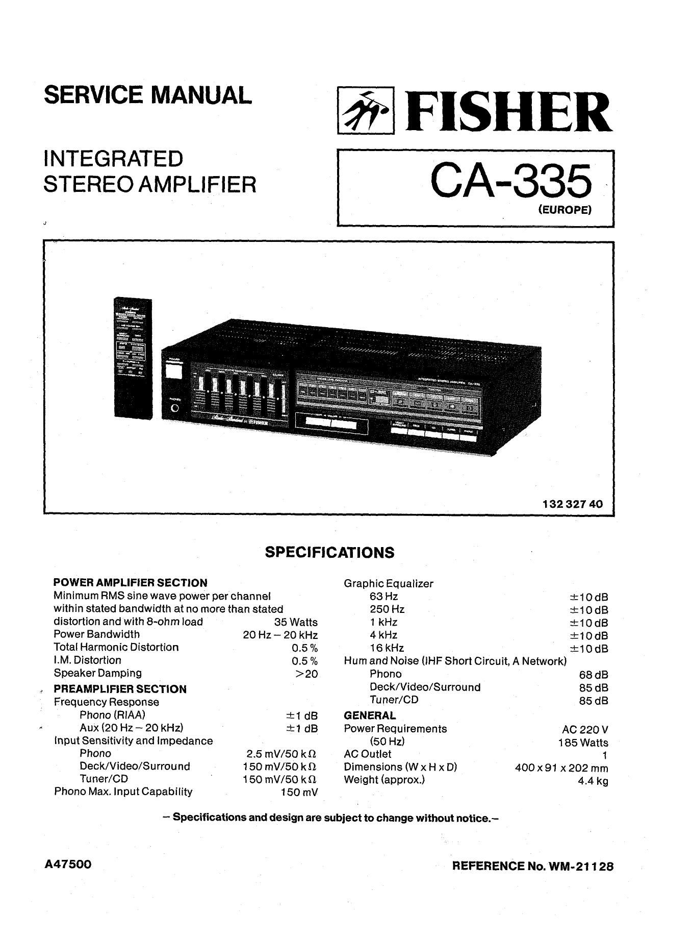
Fisher CA 335 Service Manual

This is the 16 pages manual for Fisher CA 335 Service Manual.
Read or download the pdf for free. If you want to contribute, please mail your pdfs to info@audioservicemanuals.com.

Page: 1 / 16
left right
Fisher CA 335 Service Manual

Extracted text from Fisher CA 335 Service Manual (Ocr-read)


Page 1

SERVICE MANUAL

INTEGRATED
STEREO AMPLIFIER

FISHER

CA-335

(EUROPE)

132 327 40
SPECIFICATIONS

POWER AMPLIFIER SECTION Graphic Equalizer
Minimum RMS sine wave power per channei 63 Hz :10 (18
within stated bandwidth at no more than stated 250 Hz :10 dB
distortion and with 8-ohm load 35 Watts 1 kHz :10 dB
Power Bandwidth 20 Hz - 20 kHz 4 kHz :L-10 dB
Total Harmonic Distortion 0.5 /0 16 kHz :10 dB
I.M. Distortion 0.5 % Hum and Noise (iHF Short Circuit, A Network)
Speaker Damping >20 Phono 68 dB
PREAMPLIFIER SECTION Deck/Video/Surround 85 dB
Frequency Response Tuner / CD 85 dB

Phono (RIAA) :1 (18 GENERAL

Aux (20 Hz ~ 20 kHz) :1 dB Power Requirements AC 220 V
input Sensitivity and impedance (50 Hz) 185 Watts

Phono 2.5 mV/SO k0 AC Outlet 1

Deck/Video/Surround 150 mV/EO kt) Dimensions (W x H x D) 400 x 91 x 202 mm

Tuner/CD 150 mV/50 k9 Weight (approx.) 4.4 kg
Phono Max. Input Capability 150 mV

- Specifications and design are subject to change without notice.-

A47500

REFERENCE No. WM-21128

Page 2

FUNCTIONAL BLOCK DIAGRAM

GRAPHIC Eu . VDLUME
ED . AMP :

Mono 0
TUNER I-GRAPHIE EGIAMP
0-. POWER AMP
cu 0-. BALANCE Lamas
runcrxun W-O SPEAKER
DECK E93227 m 737 5dr: IdB OUTPUT
[RID 0-.
we ELECTRIC VOLUME
[W0 O->
P/ B O---o
VIDEO/SURROUND G) e
PHONU
733E?
FUNCTIEIN
amen MANUAL
SYSTEM coNTRoI. I
DECK TlNER -
vmzo/suRRounu RELAY
- voLLIME UP -Kl-
REMOTE CDNTRUL -
TRANSMITER II: VOLUME DOWN POWER TRANS
- (MAIN)
MANUAL
MPDGIZEG .LC6522H CZISWITCH
inER
- REMDTE
fi comm. I 1 snITcn
PRE AW II:

pRCIonA
POWER MUTING AC
VOL "5: STANDBY POWER SUPPLY ---O
galED/SURRDUID , >
We: W./Lw FM ROVER TRANS

(SUB)

POWER AMPLIFIER ADJUSTMENT

BEFORE ADJUSTMENT
Unplug the AC power cord and set the front panel controls as follows:
0 Power Switch to OFF position.

0 Set the volume level to minimum level by Pressing the VOLUME DOWN button.

0 IDLING CURRENT ADJUSTMENT VR101/VR102 (on the Main P.C.Board) setting to mechanical center
position.

0 Connect the AC power cord and Power Switch to the ON position.

IDLING CURRENT ADJUSTMENT

This adjustment is very sensitive to changes in ambient temperature. Allow set to operate for 2 minutes
before attempting this alignment.

LEFI' AMPLIFIER RIGHT AMPLIFIER

1) Connect the DC Voltmeter between Pins TP1 and TP2 1) Connect the DC Voltmeter between Pins TP3 and TP4~

on the Main P.C.Board. on the Main P.C.Board.

2) Adjust the VR101 for an indication of 3mV i 0.5mV on 2) Adjust the VR102 for an indication of 3mV i0.5mV on

the DC Voltmeter. the DC Voltmeter.