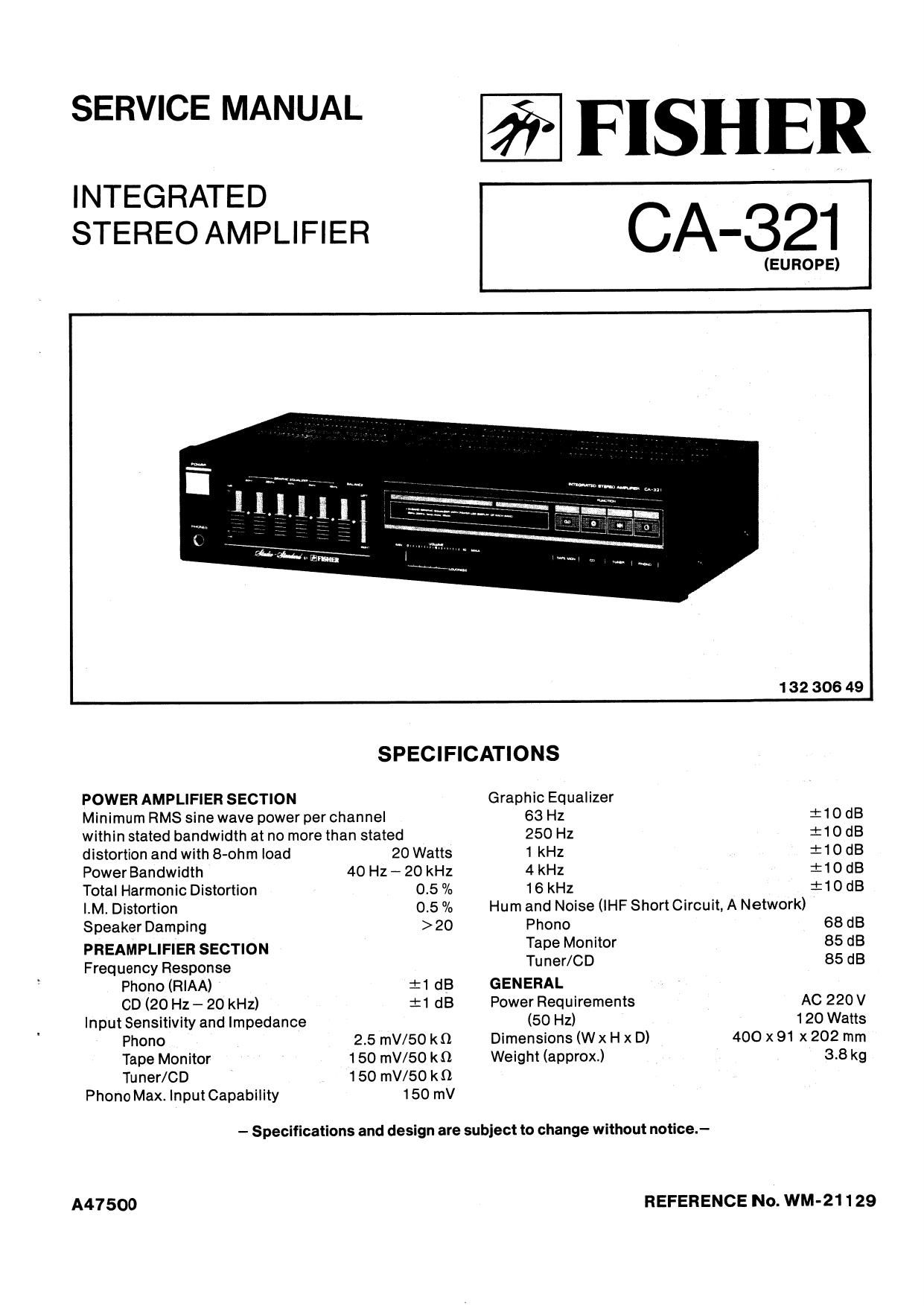
Fisher CA 321 Service Manual

This is the 8 pages manual for Fisher CA 321 Service Manual.
Read or download the pdf for free. If you want to contribute, please mail your pdfs to info@audioservicemanuals.com.

Page: 1 / 8
left right
Fisher CA 321 Service Manual

Extracted text from Fisher CA 321 Service Manual (Ocr-read)


Page 1

SERVICE MANUAL

INTEGRATED
STEREO AMPLIFIER

FISHER

CA-321

(EUROPE)

1 32 306 49
SPECIFICATIONS
POWER AMPLIFIER SECTION Graphic Equalizer
Minimum RMS sinewave power perchannel 63 Hz i10dB
within stated bandwidth at no more than stated 250 Hz :10 dB
distortion and with 8-ohm load 20 Watts 1 kHz :10 dB
PowerBandwidth 40 Hz-20 kHz 4kHz itodB
Total Harmonic Distortion 0.5 /a 16 kHz :10 dB
LM. Distortion 0.5% Hum and Noise (lHFShortCircuit,ANetwork)
Speaker Damping >20 Phono 68 dB
PREAMPLIFIER SECTION Tape Monitor 85 dB
Frequency Response Tuner/CD 85 dB
Phono (RIAA) 4:1 dB GENERAL
CD (20 HZ- 20 kHz) :1 dB Power Requirements AC 220 V
Input Sensitivity and Impedance (50 Hz) 120 Watts
Phono 2.5 mV/50 kn Dimensions (Wx H x D) 400 x 91 x 202 mm
Tape Monitor 150 mV/50 k0. Weight (approx.) 3.8 kg
Tuner/CD 150 mV/50 k0
Phono Max. Input Capability 150 mV

- Specifications and design are subject to change without notice.-

A47500

REFERENCE No. WM-21129

Page 2

CABINET & CHASSIS PARTS LIST/EXPLODED VIEW

ReI.

No. Part No.

Description (My

PACKAGE
131-6-1169-19907
131 -6-3009-36250
131 -6-3009-36260
131-6-3069-16350
181-6-4559-11200
141-6-251922390

ACCESSORIES
131-6-2719-10401
131-6-4559-11200
141 -&45 1 9-27839
142-6-41 19-33791

CABINET
4-237921520
4-2379~21524
131-6455941200
141 -2-472907 1 00
1 131-0-1016-46501
131-2-11 10-39501
131-2-11 10-39610
131~2-1203-69001
131-2-1801-16200
1314460846600
2 131-2-1410-34400
3 131-2441044900
4 131-2-1601-86200
5 131-2-1601-96701
6 131-2-1601-99600
7 131~2~1801-12900
B 131-2-3202-15900
9 131-2-3301-32300
10 131-2430541501
11 131-2431048400
12 131-2-3604-16700
13 131-2-3614-20300
14 131-2-3614-21800
15 131-2420147800
16 131-2-4201-25200
17 131-2421920200
18 131-2-5205-34900
19 131-2-6101-31800
20 131~2-6103-27200
21 131-261 1 1-14200
22 131-2-6201-37700
23 141-2-1659-68800
24 141-2421933101
25 141-2-4219-43300

31 141-0-1939-26630
32 141v0-1939-26640
33 141-0493926550
34 141-0-1939-26660
35 141-0-1939-26670
36 141-0493946680
37 141-0-1939-26690
SB 4-2229-77640
39 A 44432-00500
40 A 4-2512-33221
41 409 047 0309

51 411 020 5706
52 411 020 6208
53 411 020 6703
54 411 020 7007
55 411 020 7700
56 411 099 9704
57 411 099 9803
58 411 021 5705
59 411 021 6603
60 411 002 8503

Box Corrugate-Exp.
Pad (Left)

Pad (Right)
Patching Sheet
Serial No. Sheet
Sheet Polyethylene

Bag Fan

Serial No. Sheet
Certificate Card
Explanatory Booklet

Terminal Lug
Terminal Lug

Serial No. Sheet
Wire Band

Cabinet Front Assy
Plate Decorate (EQ)
Plate Decorate
Cabinet Front

Leg

Filter

Cover

Cover Bottom

Knob (Power)

Knob (Function)
Knob (Volume)

Leg

Metal Relntorce
Chassis

Panel Rear

Metal Support

Metal Mount Switch
Mount P.C.B.

Mount P.C.B.

Screw Ground
Screw. Brazier Hd. Tapping-B. + M3.0X6
Shaft

Cushion

Plate Shield

Cover Shield
Bushing (4N-4)

Plate Heat Sink
Knob Cap

Screw. Bind Hd. Tapping-B. +M3.0X8
Screw. Bind Hd. Tapping-C. + M4.0X10

Main Amplifier P.C.B. Assy
Graphic EQ. P.C.B. Assy
Volume P.C.B. Aasy
Power Switch P.C.B. Assy
Speaker Out P.C.B. Assy
Power Supply P.C.B. Assy
AC Seled P.C.B. Assy
Slide Volume Unit

Power Cord

Power Trans

IC STK4132MK2-S [I0301]

SCH @TPG ERZ 2.6X8
SCH S-TPG BRZ 3X12
SCR STPG BRZ 3X16
SCH S-TPG BRZ 3X20
SCR S-TPG BRZ 3X6
SCR S-TPG BRZ 8X6
SCR S-TPG BRZ 3X8
SCR S-TPG BIN 3X6
SCR S-TPG BIN 3X8
SCR PAN 3X6

.45.... .tm_._._._.

each...dabNa»q...~......~..5...._._.~_._..._.a_._._.

_._._t.._..._._._._._.

mummwmmmmm

Rel.
No.

Part No. Descriptlon OW

NOTES:

1. Parts order must contain Model 'Number, Part Number and De-
scription.

2. Ordering quantity of screws and resistors must be multiple at 10
pcs.

PRODUCT SAFETY NOTICE

Each precaution in this manual should be followed during servin
ing. Components identified with the IEC symbol A in the parts list
and the schematic diagram designate components in which satety
can be of special significance. When replacing a component iden-
titted with A. use only the replacement parts designated. or parts
with the same ratings of resistance, wattage or voltage that are
designated in the parts list in this manual. Leakage-current or re-
sistance measurements must be made to determine that exposed
parts are acceptably insulated from the supply circuit before re-
turning the product to the customer.