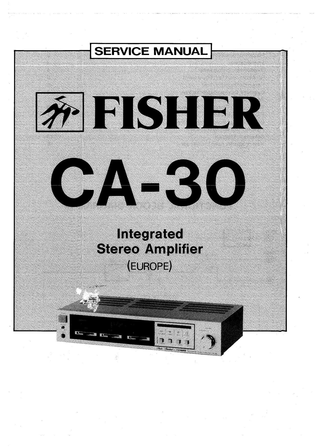
Fisher CA 30 Service Manual

This is the 15 pages manual for Fisher CA 30 Service Manual.
Read or download the pdf for free. If you want to contribute, please mail your pdfs to info@audioservicemanuals.com.

Page: 1 / 15
left right
Fisher CA 30 Service Manual

Extracted text from Fisher CA 30 Service Manual (Ocr-read)


Page 2

CONTENTS

Functional Block Diagram ................................................................ 2
Specifications ............................................................................. 3
Disassembly Instructions ................................................................. 4
Recommended Test Equipments ......................................................... 5
Harmonic Distortion Test ................................................................. 5
Cabinet & Chassis Exploded View ....................................................... 6
Parts List ................................................................................... 7
IC Equivalent Circuit & Block Diagram ................................................... 8
P.C.B.AssyPartsList ............... 9,10,11
Printed Circuit Board (Bottom View) ............................................ 12,13,14
Point to Point Wiring Diagram ........................................................ 15,16
Schematic Diagram .................................................................. 17,18
Semiconductor Lead Identification ..................................................... 19

FUNCTIONAL BLOCK DIAGRAM

PHONO
©-> 50 Amp.
TUNER TUNER l PHONO
. Pre Amp.
FUNCTION
SW
REC OUT I TAPE IN I
Power/imp,
Butter
Amp 10 STK 2025- Speaker Speaker

SW System
-é\o-fi e
Protector

Balance Volume Fuse

Bass Treble

Page 4

DISASSEMBLY INSTRUCTIONS

A. REMOVAL OF DECORATIVE PANEL

0 Detach Cover by removing six screws.
0 Pull outVOLUME knob.

c When Decorative Panel is removed from Chassis, the screw tightened through the Top and Battom
can be removed after the screw (A), as shown in Figs. 1 and 2, has been removed.

DUDE]

IT?

(FRONT PANEL REAR VIEW) Fig. 1

B. REPAIR AND ADJUSTMENT OF PRINTED CIRCUIT BOARD

o The removal of Cabinet Bottom Plate (B), will give an access to the repair or adjustment work of
Printed Circuit Board.

H n F] nnnn

(BOTTOM VIEW) Fig. 2

Page 7

PARTS LIST

as)!" Part No. Description Oty I143. Part No. Description Qty
PACKING PARTS LIST 11 131 2 1410 27600 Cover 1
3 9415 10300 Bag Polyethylene 1 12 131 2 1801 12900 Leg (Rear Panel) 2
131 6 1169 03126 Box CorrugateEXP 1 13 131 2 3101 71300 Metal Mount 10 1
131 6 2119 02131 Bag Polyethylene-EXP 1 14 131 2 3301 28900 Chassis 1
131 6 3009 33470 Pad 1 15 131 2 3306 37425 Panel Rear 1
131 6 3069 16840 Patching Sheet 1 16 131 2 3614 20300 Mount P.C,Br 2
131 6 4559 10900 Manufacturing No, 2 17 131 2 4201 17800 Screw Ground 1
141 6 1449 88300 Pad (Left) 1 18 131 2 4221 00600 Rivet 2
141 6 1449 88400 Pad (Right) 1 19 131 2 6111 14200 Bushing (LineCord) 1
20 141 2 3519 66600 Metal Mount (Right) 1
21 141 2 3519 66700 Metal Mount (Lett) 1
ACCESSORIES PARTS LIST 22 141 2 3689 10900 Plate HeatSink 1
131 6 2719 10801 Bag Fan 1 23 141 2 4729 07100 Wire Band 5
131 6 4519 15700 Guarantee Certificate 1
131 6 4559 10900 Manufacturing No, 1
142 6 4119 31868 Explanatory Booklet 1 ELECTRICAL PARTS LIST
25 A 4 2359 74032 2P Socket With/Nut 2
26 A: 4 2432 00140 Line Cord 1
CABINET & CHASSIS PARTS LIST 27 A 4 2512 22320 Power Trans 1
1 131 2 1410 27401 Dover 1 28 141 0 1939 02300 Main Amplifier P.C1B.Assy 1
2 131 2 1601 64106 Knob (Function Switch) 4 29 141 0 1939 02310 Power Switch P.C.BrAssy 1
3 131 2 1601 69602 Knob {Speaker Switch) 1 30 141 0 1939 02320 Tone/ Balance P.CB.Assy 1
4 131 2 1601 71001 Knob (Bass Treble Balance] 3 31 141 0 1939 02330 PowerlND.P10.B.Assy 1
5 131 21001 86203 Knob lPowerSwitch) 1
6 131 21601 87100 Knob (Volume) 1
7 131 21801 16200 Leg (FrontPaneI) 2 NOTES:
8 141 21119 98300 Cabinet Front 1 1, Parts order must contain Model Number, Part Number and
9 141 2 1449 58100 Plate Decorate 1 Description
10 4 2379 21520 Terminal Lug 2 2. Ordering quantity of screws and resistors must be multiple of
10 post
PRODUCT SAFETY NOTICE

Each precaution in this manual should be followed during servicing. Components identified with the IECV symbolAin the
parts list and the schematic diagram designate components in which safety can be of special significance. When replac»
ing a component identified with 0 use only the replacement parts designated, or parts with the same ratings of resis-
tance, wattage or voltage that are esignated in the parts list in this manual.

Leakage-current or resistance measurements must be made to determine that exposed parts are acceptably insulated
from the supply circuit before returning the product to the customer