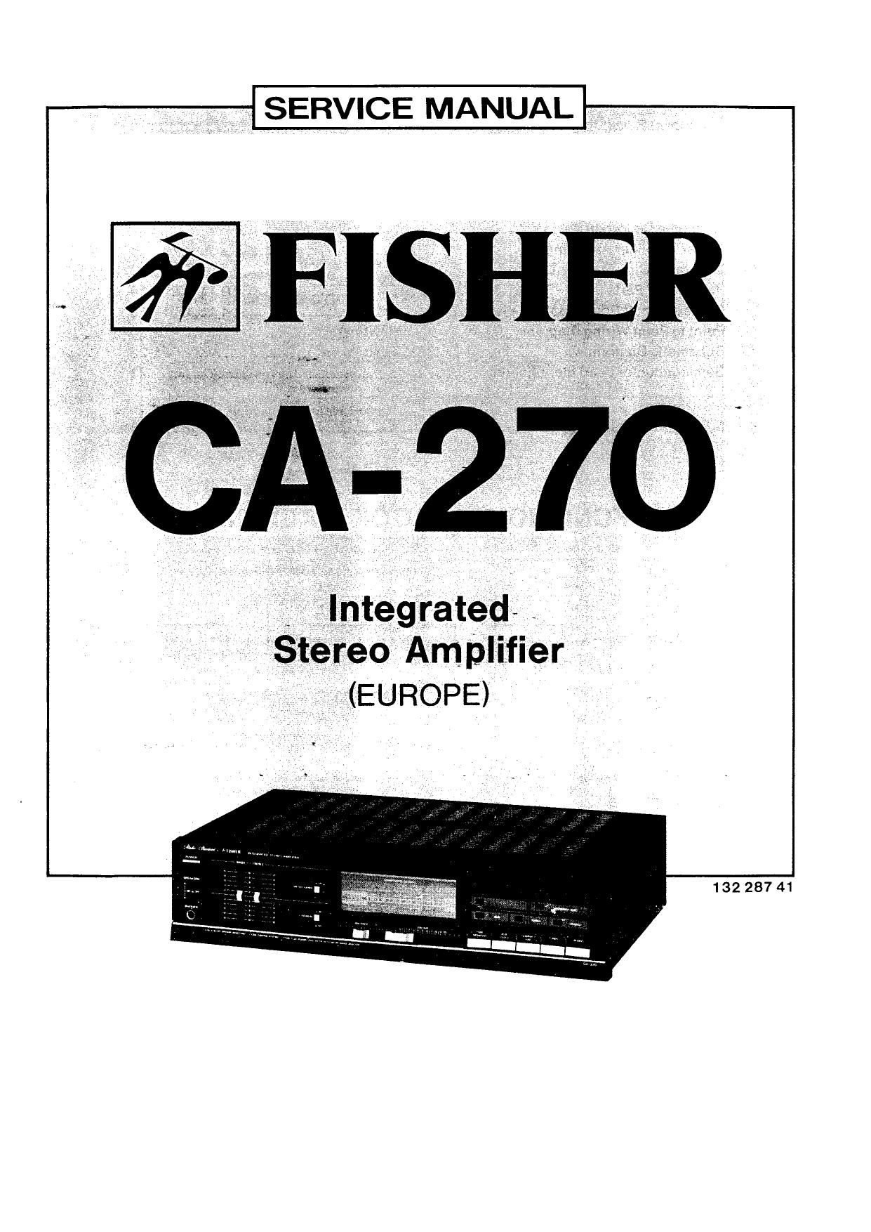
Fisher CA 270 Service Manual

This is the 19 pages manual for Fisher CA 270 Service Manual.
Read or download the pdf for free. If you want to contribute, please mail your pdfs to info@audioservicemanuals.com.

Page: 1 / 19
left right
Fisher CA 270 Service Manual

Extracted text from Fisher CA 270 Service Manual (Ocr-read)


Page 1

SERVICE MANUAL


132 287 41

Page 2

CONTENTS

Functional Block Diagram .............................................................. 2
Specifications .................

Cabinet & Chassis Exploded View I

Parts List ...................................

Recommended Test Equipments ....................................................... 7
Harmonic Distortion Test ................................................................. 7
Power Amplifier Adjustment .............................................................. 8
integrated Circuit Block Diagram ....................................................... 8,9
P.C_B.Assy Parts List 10.1 1,12.13,14
PrintedCircuitBoard (Bottom View) 14,15,16,17,18
Point to Point Wiring Diagram ...........................

Schematic Diagram .....................................

Semiconductor Lead Identification ..................................................... 23

FUNCTIONAL BLOCK DIAGRAM

FUNCTION TAPE MONITOR
E0 Am
Input 9

a
I


Tone C:"1roi

399359.115} 57mm steer

*4" Soeakers :«

.

Page 14

2:." Part No. Description Oty
CAPACITOR
0301 A 4-2239-70970 Capamlor 0.0qu 400V new 1
RESISTOHS PRODUCT SAFETY NOTICE
R175 RH5A61202-JZOOO Metal 560$) 2W 15% 1
R176 RDZ-2-1251-JM000 Carbon 220;: MW 25% 1 Each precaution in this manual should be followed
R177 R02.7.1251.Jmooo Carbon 270 MW 15% 1 during servicing. Components identified with the IEC
R275 HHS-6420242000 Metal 5501) 2w 15% 1 symbol A in the parts list and the schematic diagram
[.1275 02.2.1251 >JM000 Carbon 2201) 114w 15% 1 designate components in which safety can be of special
54277 02.742514MQoo Cam 27011 um 455% 1 significance. When replacing a component identified
with A, use only the replacement parts designated, or
pads with the same ratings of resistance, wattage or
NOTES- voltage that are designated in the parts list in this manual,
1 P ti d . Leakage-current or resistance measurements must be
, ars _or' er must contain Model Number, Part Number and made 0 determine that exposed parts are acceptably
Descrfphon' I , . insulated from the supply circuit before returning the
2, :Dédglsng quantlty of screws and resrstors must be multiple of product to the customer.

SWITCH P.C.BOARD

(BOTTOM VIEW)


4© rt-T--~r_-'I
, E _ L__.I___._.I..__I
3Q 5Q FuszTioAxa
rfiT-_fr'fi
6 Q * _I....>.I....._J+_.a
_I

'-H-*C30l I
in"? i
| \ l |
l \ l I
l - l l
| l .I r-
| l H -
| | 'l l.
I I ~\--II,-
l I H
r:::rI-1-1:|_ ___ _ _ll '
| | ___i__l T T |
t__l L_J L_J :
swaoe sw409 SW4lO l
POWER SPEAKER SPEAKERL-g-
sw A SW, 8 sw. r
ON ON ON L___~J
HEADPHONES
OFF OFF OFF JACK

_14_